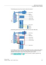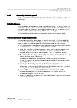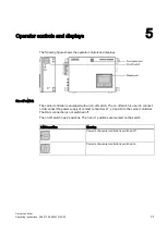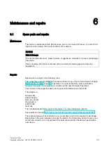
Mounting and connection
4.3 Mounting the carrier controller
Carrier controller
18
Operating Instructions, 09/2013, A5E03474162-02
Bolting surface
The bolting surface must support the weight of the carrier controller and meet the following
requirements:
Material property
Value
Material thickness
2 to 6 mm
Planarity
≤
0.5 mm
Clearance
You need to provide the following clearance around the carrier controller:
On all sides, except on the rear
50 mm
Rear side
20 mm
This restriction does not apply to situations in which a component of the EMS plant briefly
passes the carrier controller at a clearance of less than 50 mm when the EMS carrier is
moving.
4.3
Mounting the carrier controller
It is not necessary to open the carrier controller for mounting.
The mounting fixture on the EMS carrier provides several options of mounting the carrier
controller:
●
Tapped holes for threaded pins or screws
●
Through-holes for threaded bolts or screws
●
Threaded bolts on the mounting surface
The bolting surface must allow for full surface contact of the fastening hooks on the carrier
controller. The fastening hooks are designed for M8 threads.
The following drill pattern shows the distances between the mounting elements.
Observe the specifications in the section "Operational requirements (Page 52)".


