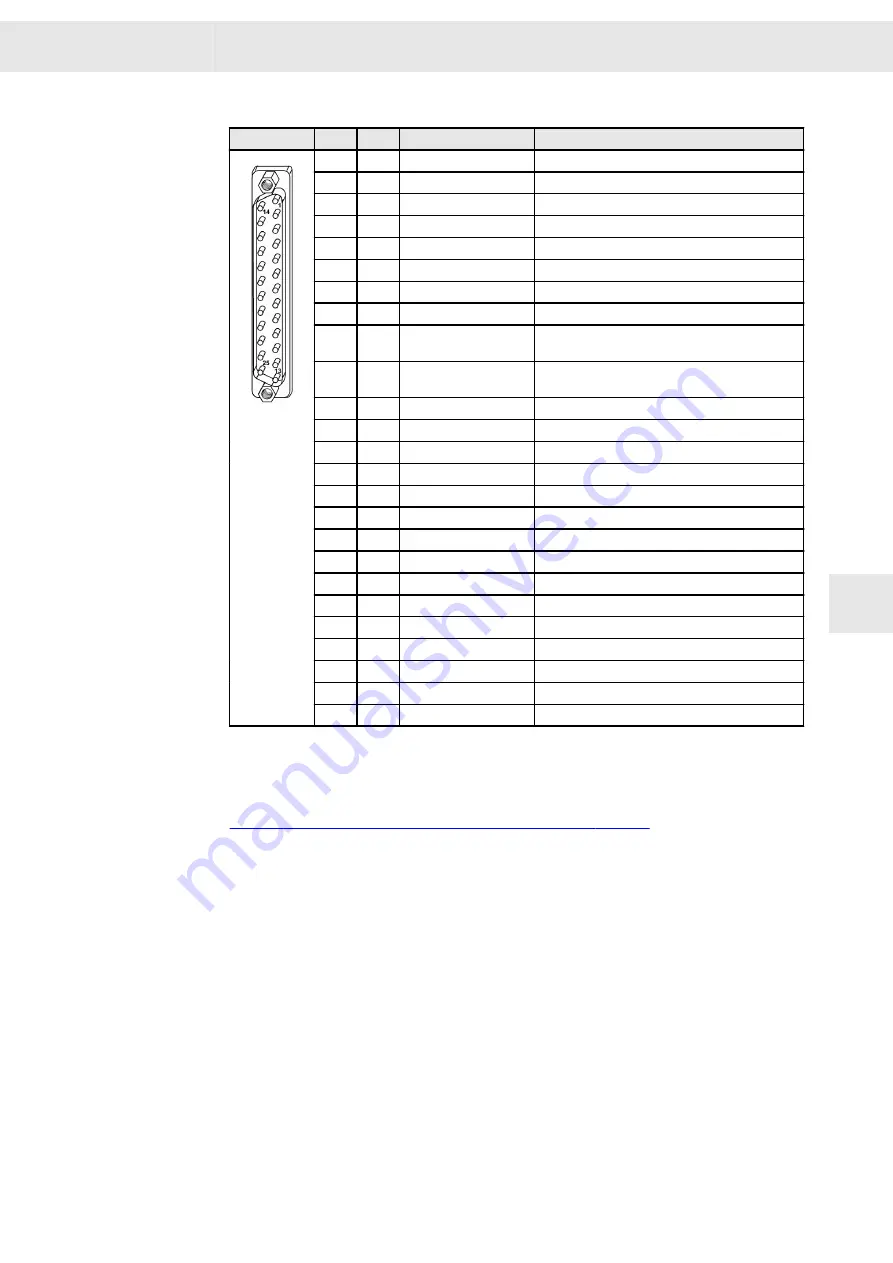
25-pole male submin D connector
X30
Pin
I/O
Name
Meaning
1
I
IN0
Switch on
2
I
IN1
Start / Stop
3
I
IN2
Error reset
4
I
IN3
Speed direction
5
I
IN4
Configuration 1/2
6
I
IN5
External hardware OK
7
n.c.
8
n.c.
9
O
UA+
Speed pulse , 6 pulses per motor revolu‐
tion
10
O
UA-
Speed pulse output -, 6 pulses per motor revolu‐
tion
11
I/O
GND
Ground
12
I/O
GND
Ground
13
I/O
GND
Ground
14
O
OUT0
Programmable digital output 1
15
O
OUT1
Programmable digital output 2
16
O
OUT2
Programmable digital output 3
17
O
OUT3
Programmable digital output 4
18
O
OUT4
Programmable digital output 5
19
O
OUT5
Programmable digital output 6
20
n.c.
21
n.c.
22
n.c.
23
I
PTC0
Do not wire
24
O
+24V
25
O
+24V
Stud bolt flange: max. tightening torque = 0.7 Nm
Related topics
Connection examples: "X30 – Digital Inputs / Outputs", page 53
8.9.1
Inputs
Switch on
When this input is activated, the control of the frequency converter is connected to
allow power transmission to the motor. The holding current is activated, if programmed.
The motor will be accelerated as soon as the start signal and a corresponding refer‐
ence value are received.
Start / Stop
The function input “Start/Stop” permits the start or stop of the frequency converter.
▶
Start = +24 V
▶
Stop = 0 V
W
Connectors
FC2 - Frequency converter 02192100xy
39
8
Содержание FC2
Страница 1: ...FC2 Frequency converter 02192100xy Hardware Description P TD 0000552 2 2019 08 26 SIEB MEYER W ...
Страница 4: ...Chapter Overview W 4 FC2 Frequency converter 02192100xy ...
Страница 8: ...Content W 8 FC2 Frequency converter 02192100xy ...
Страница 12: ...General Information W 12 FC2 Frequency converter 02192100xy 2 ...
Страница 22: ...Unit Assembly Complying EMC W 22 FC2 Frequency converter 02192100xy 4 ...
Страница 30: ...Technical Data W 30 FC2 Frequency converter 02192100xy 7 ...
Страница 48: ...Connectors W 48 FC2 Frequency converter 02192100xy 8 ...
Страница 70: ...Safety Circuit Restart Lock STO W 70 FC2 Frequency converter 02192100xy 12 ...


