Prerequisites
•
You are registered as a service technician.
•
The value for Stop Field radius was calculated during project planning.
•
The value for Reduced Field radius was calculated during project planning.
Approach
1.
Click on
Fields
.
2.
Select mode.
°
Free Fields
No distances are configured in this mode. Responsibility for safe design of
the protective fields thus lies with the person who carries out commissioning.
°
Robot Centric
Distances are configured in this mode. These distances are circular with the
robot base at the center of the circle. The distances are displayed during
commissioning and are taken into account in the automatic generation of
fields.
3.
Enter values for safety-relevant distances.
Table 4: Parameters in the Fields tab
Distance
Description
Warning Field radius
Distance of the warning field to the robot.
Reduced Field radius
The calculated minimum distance for trig‐
gering the safety-rated monitored speed.
Stop Field radius
The calculated minimum distance for trig‐
gering the protective stop.
4.
Click on
Apply
.
✓
The
Success
dialog is displayed. Confirm dialog to continue.
Complementary information
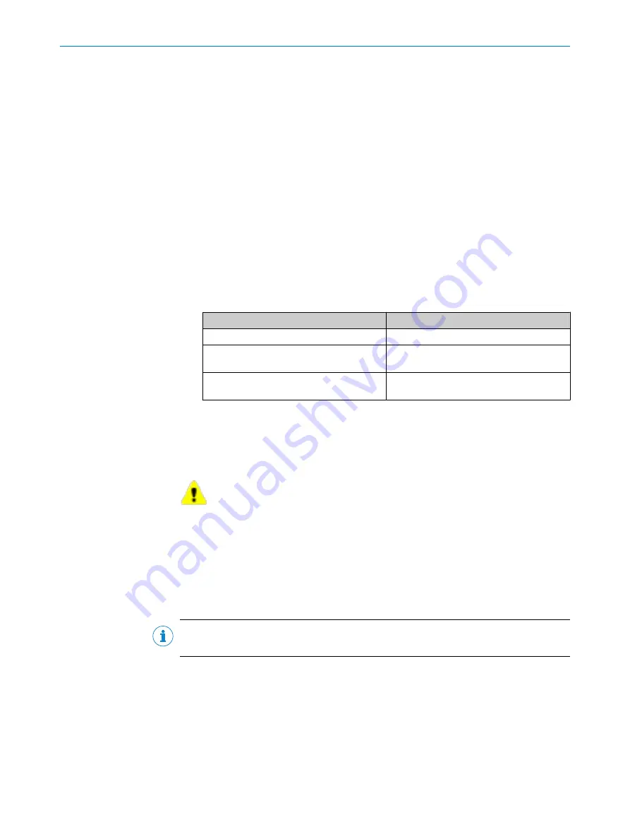
Safety-relevant values are marked with the following symbol:
Further topics
•
"Calculating value for Stop Field radius", page 9
•
"Calculating value for Reduced Field radius", page 11
6.3.3.5
Configuring information for application
Important information
NOTE
These settings are optional and not required for operation of the safety system.
Prerequisites
•
You are registered as a service technician.
Approach
1.
Click on the
App
tab.
2.
In the
Application name
and
Project name
fields, enter the desired information.
3.
Click on
Apply
.
✓
The
Success
dialog is displayed. Confirm dialog to continue.
CONFIGURATION
6
8025720/1A9R/2020-12-15 | SICK
O P E R A T I N G I N S T R U C T I O N S | nanoScan3 Tool - URCap
19
Subject to change without notice


