Chapter
10
Operating instructions
ICR 84x Image Code Reader
10-8
©
SICK AG · Division Auto Ident · Germany · All rights reserved
8 010 961/0000/10-05-2005
Appendix
2.
Enable TCP/IP communication.
Configure the IP adresses of the ICR and the PC.
Chapter 5.5.6 Connecting the Ethernet interface, Page 5-10
10.3.4
CLV Setup user interface
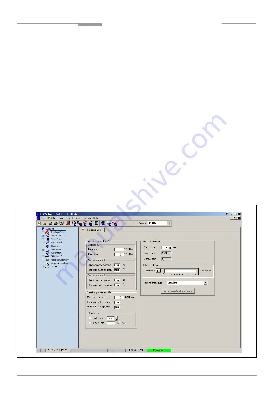
The graphical user interface (GUI) of CLV Setup is largely self explanatory. The online CLV
Setup Help function provides a description of how to use the program under the menu item
H
ELP
TO
CLV S
ETUP
in the navigation tree.
shows the user interface.
The programm window of the user interface comprises the following elements:
•
Title bar that displays the program name, current configuration file and status
(e.g. “No File“)
•
Menu bar with pull-down menus
•
Toolbar with buttons for triggering various functions
•
Drop-down list (top right) for selecting the device type
•
Frame for displaying the navigation tree of the tabs (on left-hand side)
•
Frame for displaying the 11 tabs for ICR 84x (Reading Configuration, Device
Configuration etc.) on right-hand side. The numbers of displayed tabs depends on the
selected items in the navigation tree on the left side. The parameters on the tabs are
grouped according to their function. Some of these parameters open further dialog
boxes.
•
A status bar (at the bottom of the window) with two display fields for the communication
activities between CLV Setup and the ICR, display of interface parameters of the PC,
error display field (system errors) of the ICR, device specification field and status display
for the connection to the ICR.
Fig. 10-2: User interface of the “CLV Setup“ software


