Automatic Tool Changer (ATC) Installation Manual • December 1, 2016
© Copyright 2016 ShopBot Tools, Inc.
page 19
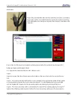
Route the gray cable from Wago connec-
tor through Y-Axis E-chain, through X-Axis
E-chain, under table, through the Roxtec
fixture on the side of the control box, and
into the control box.
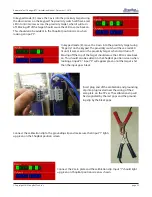
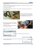
Connect the yellow, green, white and brown wires to the ATC Interdace Board inside the control box as per
the picture below. Connect the yellow wire (cooling air) to the +24V terminal at the front of the ATC Inter-
face Board. It will share this terminal with a brown wire from the z-proximity cable. Connect the green wire
(ground) to the GND terminal of the Tool Release terminal block. Connect the white wire (tool release) directly
above the green to the TR+ terminal of the Tool Re-
lease terminal block. Lastly connect the brown wire
(dust skirt) to the DS+ terminal of the Dust Skirt termi-
nal block.


