Automatic Tool Changer (ATC) Installation Manual • December 1, 2016
© Copyright 2016 ShopBot Tools, Inc.
page 17
Wiring the Proximity Switches and Z Zero Plate
Run cables from proximity switches and Z zero plate through the Roxtec opening into the control box.
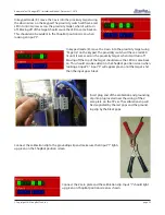
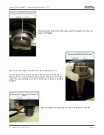
Locate the proximity switch on the back side of the Z-axis, located
just under the Z-axis motor. Using the 90-degree proximity switch
cable, plug the cable onto the back of the proximity switch and
screw the connection tight with the thumb screw. Route the cable
through the Y-axis E-chain and into the control box. Ensure there
is proper clearance between the switch and E-chain to prevent
interference or tension during movement.
Proximity Switches
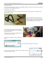
Connect the black proximity switch cable for the X-axis into input 2 (2/PX) on the blue terminal block on the
control board inside the control box. Connect the black proximity switch cable for the Y-axis into input 3 (3/PY)
on the same blue terminal block on the control board.
Connect the Z-axis proximity switch into input 5 (IN5) terminal block. The blue wires from all of the switches
can be connected to any of the grounds (GND) on the board if necessary. The brown wires from all three of the
switches will be connected to the “+24V” position on the blue output terminal block. To make wire insertion
easier, the terminal blocks can be removed by pulling them straight off the board.
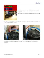
When the control box is powered up, a red LED in the body of the proximity switch on the tool will stay bright
until it is triggered by coming near a target.


