Shin-Nippon SLM-4000 Скачать руководство пользователя страница 37


RB-473-C02G 


34

3)


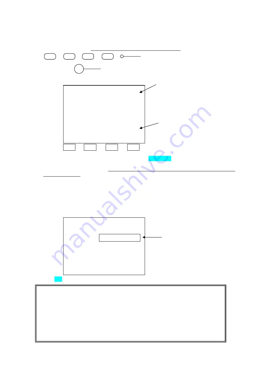
Start up SLM-5000/SLM-4000 with PROGRAM MODE.   
SLM-5000  :  Press  five  switches 

quickly

  in  the  following  order  immediately  after  the  power  LED 

illuminates.   

SLM-4000  :  Press  five  switches 

quickly

  in  the  following  order  immediately  after  the  power  LED 

illuminates. However, press switch 

  longer than 1 second. 


The screen shown below appears. 


                                  4800          9600          19200        38400 

4)


Connect the cable between SLM-5000 and PC, and click Data Output on the PC screen. 
Leave the equipment until the data output completes. It may take about ten minutes to transmit the data 
but it depends on the bps setting. (Three green belts on the SLM-5000 / SLM-4000 screen indicate the 
end of transmission.)   
 
Note

  When  ERR  appears  on  the  screen  of  SLM-5000  /  SLM-4000,  the  bps  setting  may  not  be 

matched or Hyper is still indicated on the screen.   


When  the  upgrading  completes,  the  message  appears  on  the  SLM-5000  /  SLM-4000  screen.  Press 
Memory/Add switch to reactivate the SLM-5000 / SLM-4000. At this time, CS:xxxx(4-dizit numbers) is 
indicated on the screen. Please write this number down and keep it.   


5)


Click Exit on the PC screen to complete the whole procedure. 


**

  PROGRAM MODE 

**


    Please Wait. 

    RECEIVE   


                            19200 bps 

    Memory Switch 

−>

  Exit 

Three belts like this appear. 

NOTE     

When you use this program, please pay attention to the followings.   

1)

  This upgrading program is a prototype. 

We do not guarantee that the program (Pwriter.exe) works with every PC and on OS. 

2)

  Contact us when you wish to upgrade your program with this program. Please note that 

SLM-5000 may be malfunctioned if upgrading does not performed appropriately.   

3)

  The upgrading program (mot File) may not be reproduced or used in any form or by any 

means. 

Immediately after the power LED illuminates 


Memory/Add switch 

**

  PROGRAM MODE 

**


        Please Send MOT File. 


                                              38400 bps 

                    Memory Switch 

−>

  Exit 

Match the bps setting to that of PC. 
You  can  change  the  setting  by 
pressing  the  panel  keys.  The  bps 
corresponds    with  each  switch  is 
as shown on the left. 


Hyper 

Delete 

Hyper

  in  red.  You  can 

delete  it  by  pressing  the  switch 
corresponding to the bps you set. 

Содержание SLM-4000

Страница 1: ...RB 473 C02G A u t o L e n s m e t e r SLM 5000 SLM 4000 Maintenance Manual...

Страница 2: ...sures against errors 19 6 1 1 Measure Error 19 6 1 2 Paper Empty 20 6 1 3 Printer Cover Open 20 6 1 4 SPH CYL Prism ADD Over 21 6 1 5 Printer Heat Over 21 6 1 6 EEPROM Fault Sensor Error 21 6 1 7 DRAM...

Страница 3: ...ication Color LCD monitor SLM 5000 Monochrome LCD monitor SLM 4000 Operations switches Indicator Marking lever Lens plate Lens stand Lens holder Memory Add switch Printer SLM 5000 Only Power switch Po...

Страница 4: ...Color LCD monitor SLM 5000 Monochrome LCD monitor SLM 4000 Operations switches Indicator Marking lever Lens plate Lens stand Lens holder Memory Add switch Printer SLM 5000 Only Power switch Power inle...

Страница 5: ...h RS 232C Power inlet Power switch Fuse x 2 EUROPE T2A L 250V UL CSA 250V 3A Printer I F board Printer Connected to FG harness green yellow Memory Add switch board Terminal Assy FG attachment Control...

Страница 6: ...CN202 2 pins Operation switch board Inverter board CN301 2 pins CN302 2 pins Control board Terminal board RS 232C Switching power supply CN2 4 pins CN1 5pin 1 3 5 L brown N light blue 1 3 FG green ye...

Страница 7: ...Control board Terminal board RS 232C CN2 4pin CN1 5pi n 1 3 5 L brown N light blue 1 3 FG green yellow GND GND 5V 5V Printer I F board CN101 20pin CN103 20pin CN102 9pin FG green yellow FG green yello...

Страница 8: ...o screws securing the lens plate M3 x L10 binding screws black 4 3 Cases Remove eight 7 screws securing right and left cases Always cut the power and disconnect the power cord before disassembling the...

Страница 9: ...nstrument on its side so that the left side when viewed from the front becomes the bottom Then raise the right side up Raise firmly Do not lose the screws when disassembling the instrument since some...

Страница 10: ...and printer onto the right case of the main unit inside Set screw C and a printer open switch are tightened together 5 Remove the connectors from the printer I F board Since CN101 of the printer I F...

Страница 11: ...bly of exterior features 2 Disconnect the harnesses and FG harness connecting from LCD ASSY to the control board LCD monitor control board Switch board control board See 2 Exploded View and 3 Wiring D...

Страница 12: ...the connector A connected to the LCD and the connector B connected the inverter board Then unscrew four screws securing the LCD monitor The LCD monitor will be removed from the LCD case C LCD monitor...

Страница 13: ...n 5 3 LCD monitor 2 Disconnect the connector A and B from the inverter board 3 Unscrew three screws to remove the board from LCD case D 4 Follow the steps above in the reverse order to reassemble the...

Страница 14: ...s from RS 232C and remove the connector connected to the control board 3 Remove FG harness in the Optical ASSY side Two screws are at the end of green and yellow wires 4 Disconnect the connector A fro...

Страница 15: ...well specification 1 Rotate the marking ASSY Affix the positioning tape for the marking ASSY on the marking arm Refer to Figure 3 on the right for the tape position to be affixed 2 Lower the lens hold...

Страница 16: ...designed for SLM 5000 4000 only Avoid touching the pen pin tip when replacing The tip may be damage so that the marking can not be done Do not fasten the screw too tightly when replacing You may dama...

Страница 17: ...ell to the side to remove from the main unit 2 Soak the specified ink into the sponge from the ink refill point 3 Attach the inkwell to the main unit Always use the specified ink for refill Avoid touc...

Страница 18: ...unit up slightly 3 Disconnect the connector inserted into the illumination light PCB ASSY 4 Remove two screws Q fixing the illumination light PCB ASSY and remove the PCB 5 Center and fix the illumina...

Страница 19: ...vers See Assemble Disassemble of Outer Cases 2 Remove two screws fixing the heavy motion damper Light motion damper and remove the heavy motion damper Light motion damper 3 Follow the steps above in t...

Страница 20: ...5000 Only Message Status Description Measure Error When the power is turned values are not initialized values are not zero 0 Paper Empty SLM 5000 Only No papers are set in the printer Printer Cover Op...

Страница 21: ...under the lens stand is dirty Measure Error appears The lens is placed on the lens stand when the power is turned on Remove the lens and turn the power off and on again Yes The lens under the lens sta...

Страница 22: ...M 5000 Only The printer cover is open Printer Cover Open appears The printer cover is properly set Set the cover properly and turn the power off and on again No Yes Replace the printer The message sti...

Страница 23: ...rol board EEPROM board or the harnesses between them when the power is turned on Printer Heat Over appears Cut the power and leave the instrument for 5 minutes or longer Then when the power is turned...

Страница 24: ...measured is abnormally dirty or has deep flaws The measurement unit is exposed to the direct sunlight or strong glare Avoid the direct sunlight or strong glare and measure again Yes The lens under the...

Страница 25: ...ght C 2002 RyuSyo Industrial Co LTD SP9043 Ver 2 02 2002 6 13 Dealer Mode Loading Copyright C 2002 RyuSyo Industrial Co LTD SP9043 Ver 2 02 2002 6 13 Dealer Mode Loading Auto Lensmeter SLM 5000 Auto L...

Страница 26: ...ues are unstable Retry Error may appear When the lens being measured is extremely dirty or has some flaws and or the lens under the lens stand is dirty A part of the measurement ring is missing The me...

Страница 27: ...ssing Memory Add 6 Then follow the same procedure for check of image to check the image See page 22 Figure 3 Menu 1 Setting 2 Freeze Image 3 Function 4 System 5 Memory 6 Calibration Off On Off On On O...

Страница 28: ...RB 473 C02G 25 When the measurement optical path is blocked and or when the electrical control system such as the measurement LED and cameras malfunctions No measurement ring...

Страница 29: ...5000 Auto Lensmeter SLM 5000 Copyright C 2002 RyuSyo Industrial Co LTD SP9043 Ver 2 02 2002 6 13 Dealer Mode Loading Copyright C 2002 RyuSyo Industrial Co LTD SP9043 Ver 2 02 2002 6 13 Dealer Mode Lo...

Страница 30: ...d press switch Check that each item is set as below Menu 1 Setting 2 Freeze Image 3 Function 4 System 5 Memory 6 Calibration Image View Image Hold Adjust On Off Off On Off On Function Dealer Mode Hand...

Страница 31: ...tion of angle to the lens plate 14 P 2 2 00 Calibration of 2 prism powers 15 P 5 5 00 Calibration of 5 prism powers 16 P 10 10 00 Calibration of 10 prism powers 17 Far point 0 12 standard value Progre...

Страница 32: ...e reach between 0 00 and 0 01 in both X and Y directions the spherical value is automatically calibrated to the value of the test lens Calibration S C A PX PY 0 00 0 00 180 O 0 00 D 0 00 00 Start Take...

Страница 33: ...lign the calibration lens according to the indication of the base direction Align B Base direction the measured value is taken in 0 45 90 135 180 225 270 315 When the measured value of the indicated b...

Страница 34: ...OK Abbe 60 CYL Step 0 01 Menu 1 Setting 2 Freeze Image 3 Function 4 System 5 Memory 6 Calibration Measuring Marking OK S C A Px Py 0 00 0 00 180 I 0 00 U 0 00 40 S Cyl Step Abbe S 25 Calibration S C A...

Страница 35: ...n and blow the large dusts or particles first If it is still dirty wipe it with a soft dry cloth When it is hard to remove stains wipe it lightly and evenly with the soft cloth moistened with a thinne...

Страница 36: ...p of PC Pwriter exe SLM 5000 SLM5000 V2 mot SLM 4000 SLM4000 V2 mot SLM 5000 SLM5000 V3 mot SLM 4000 SLM4000 V3 mot 2 Start up Pwriter exe A window that includes four keys below appears File Select Da...

Страница 37: ...reactivate the SLM 5000 SLM 4000 At this time CS xxxx 4 dizit numbers is indicated on the screen Please write this number down and keep it 5 Click Exit on the PC screen to complete the whole procedure...

Страница 38: ...lowing is the communication procedure using Hyper Terminal of Windows95 English version Main screen of Hyper Terminal Adjustment data of SLM 5000 SLM 4000 which is stored in the EEPROM on the camera b...

Страница 39: ...5 5 6 6 7 7 8 8 Connection sample 2 D Sub 9pin female D Sub 9pin female SLM 5000 SLM 4000 Connection PC 1 1 2 2 3 3 4 4 5 5 6 6 7 7 8 8 Connection sample 3 D Sub 9pin female D Sub 25pin male SLM 5000...

Страница 40: ...er to 7 Image Assessment 3 Call up Hyper Terminal indicates a click and a double click Start Programs Accessories Hyper Terminal Hypertrm 4 Enter a connection name and select the icon Click OK You can...

Страница 41: ...me and area code Select Direct to Com 1 and click OK 6 Set each setting shown on the right as below Bits per second 38400 Data Bits 8 Parity None Stop bit 1 Flow control Hardware Click OK when the set...

Страница 42: ...the second page of 1 Setting and set each parameter as follows BaudRate 38400 Character 8 Parity None Stop bit 1 PC File Properties A window shown in 5 appears Configure A window shown in 6 appears se...

Страница 43: ...4 Output of adjustment data 1 Start receiving the data Create a text file txt with Notepad Transfer Capture Text 2 Store the adjustment data Input the file name created in 1 and click Start Start rec...

Страница 44: ...nding the data Press MENU switch and call up the menu Select 2 Output Memory in 5 Memory or 4 Memory 4 When the buzzer sounds sending data completes 5 Completes receiving the data Transfer Capture Tex...

Страница 45: ...4 Memory The message Please Send Data 100 appears on the bottom of the screen and the number decreases While the number decreases SLM 5000 is waiting for receiving the data Perform the step 2 at this...

Страница 46: ...nal the file may be corrupted Check the file name and repeat the procedure from 11 5 1 Cut the power of SLM 5000 and turn it on again Note Before communication Use the cable with appropriate specifica...

Отзывы: