Appendix
Connecting Pin Assignments
RS-232C Port:
9-pin D-sub male connector of the DIN-D-sub RS-232C cable
Pin No.
Signal
Name
I/O
Reference
1
Not connected
2
RD
Receive Data
Input
Connected to internal circuit
3
SD
Send Data
Output
Connected to internal circuit
4
Reserved
Connected to internal circuit
5
SG
Signal Ground
Connected to internal circuit
6
Reserved
Connected to internal circuit
7
Reserved
Connected to internal circuit
8
Reserved
Connected to internal circuit
9
Not connected
6 7 8 9
1 2 3 4 5
INPUT 2 COMPONENT/RGB Port:
15-pin Mini D-sub female connector
•
RGB Input
Pin No. Signal
1
Video input (red)
2
Video input
(green/sync on green)
3
Video input (blue)
4
Not connected
5
Composite sync
6
Ground (red)
7
Ground (green/sync on green)
10
9
8
7
6
15
14
13
12
11
5
4
3
2
1
Pin No. Signal
8
Ground (blue)
9
Not connected
10
Ground
11
Ground
12
Bi-directional data
13
Horizontal sync signal
14
Vertical sync signal
15
Data clock
•
Component Input
Pin No. Signal
1
Video input P
R
(C
R
)
2
Video input Y
3
Video input P
B
(C
B
)
4
Not connected
5
Not connected
6
Ground (P
R
)
7
Ground (Y)
Pin No. Signal
8
Ground (P
B
)
9
Not connected
10
Not connected
11
Not connected
12
Not connected
13
Not connected
14
Not connected
15
Not connected
Downloaded From projector-manual.com Sharp Manuals
(RS-232C) Specifications and Command Settings
•
P
P
I
I
I
I
O
O
V
V
V
V
W
W
E
E
E
E
R
R
D
D
D
D
_
_
_
_
_
_
_
_
_
_
_
_
_
_
_
_
_
_
1
0
1
2
3
4
BUTTONS & REMOTE CONTROL BUTTONS
Downloaded From projector-manual.com Sharp Manuals
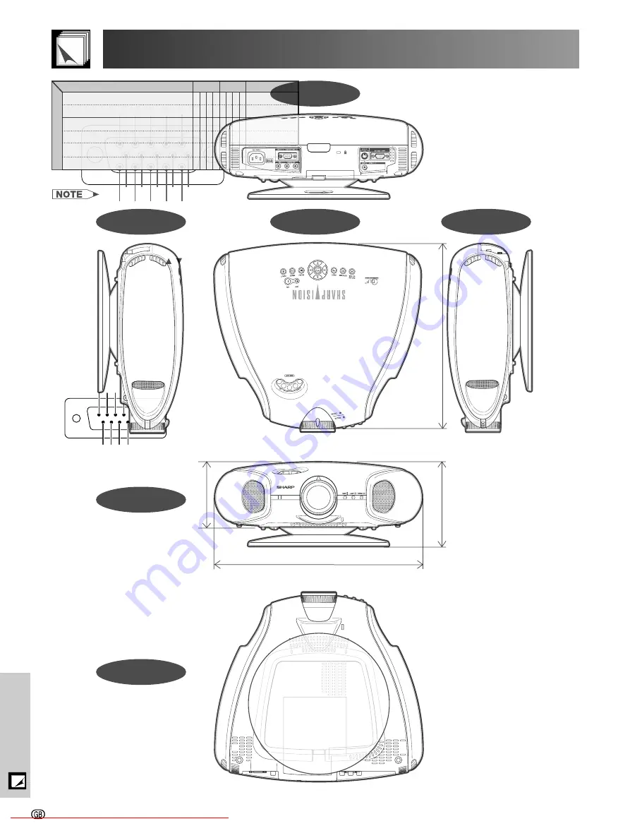
Dimensions
Units: mm
Front View
Bottom View
Side View
Top View
Side View
Rear View
Downloaded From projector-manual.com Sharp Manuals
Glossary
Aspect ratio
Auto Sync
Background
Clock
CLR Temp (Colour temperature)
Composite sync
Digital keystone correction
Digital shift
GAMMA
Intelligent compression and expansion
’
Phase
RESIZE
RS-232C
Stretch
Sync on green


