8
VC-A412U/A413U
VC-H812U/H813U
VC-H812U/H813U
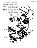
MECHANISM CHASSIS
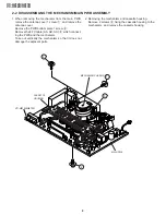
2-2 DISASSEMBLING THE MECHANISM/MAIN PWB ASSEMBLY
1. When removing the mechanism from the main PWB,
remove the antenna cover 1 screw
1
, and remove the
antenna cover.
Remove the PWB bottom plate 1 screw
2
.
Remove the FFC cable (AA, AD, AH)
3
which connect-
ing the PWB and the mechanism.
Take out vertically the mechanism so that it does not
damage the adjacent parts.
2. Removing the mechanism and cassette housing.
Remove 2 screws
4
fixing the cassette housing to the
mechanism, and remove the cassette housing.
2
1
3
4
CASSETTE
HOUSING
MAIN PWB
Содержание VC-A412U
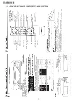
Страница 6: ...6 VC A412U A413U VC H812U H813U 1 3 LOCATION OF MAJOR COMPONENTS AND CONTROL ...
Страница 50: ...VC A412U A413U VC H812U H813U VC A412U A413U VC H812U H813U 50 51 8 BLOCK DIAGRAM SYSTEM SERVO BLOCK DIAGRAM ...
Страница 53: ...56 VC A412U A413U VC H812U H813U POWER CIRCUIT BLOCK DIAGRAM ...
Страница 63: ...72 VC A412U A413U VC H812U H813U M E M O ...


