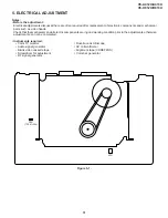


45
VC-A412U/A413U
VC-H812U/H813U
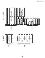
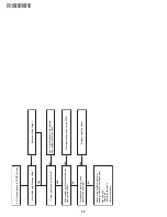
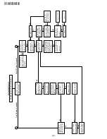
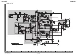
Picture E-E does not appear.
Is picture signal input into pins(30) and (31) of IC201?
YES
YES
YES
YES
YES
YES
NO
NO
NO
NO
NO
NO
NO
NO
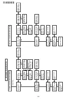
1
External input mode
Check the line between the rear video input terminal
and pin(30) of IC201.
2
U/V tuner mode
Check the line between the pin(25) of U/V tuner and
pin(31) of IC201.
Is picture signal output to the pin(52) of IC201?
Is picture signal input into the pin(49) of IC701?
Is picture signal output to the pin(47) of IC701 ?
Check the line between pin(52) of IC201
and pin(49) of IC701.
Check the line between pins(63) and (62) of
IC201 and pins(56) and (57) of IC701.
Is picture signal output to the emitter of video output
buffer (Q251)?
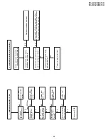
1
Line output: Check Q251 periphery and output terminal periphery.
2
RF output: Check Q251 periphery and tuner pin(6) periphery.
Is 5V applied to the pins(12), (61) and (90) of IC201?
Is 5V applied to the pin(51) of IC701?
Check the YC 5V line.
Check the AT 5V line.
Is serial data clock signal applied to the
pins(63) and (62) of IC201?
Check Q251 periphery.
FLOW CHART NO.18
Содержание VC-A412U
Страница 6: ...6 VC A412U A413U VC H812U H813U 1 3 LOCATION OF MAJOR COMPONENTS AND CONTROL ...
Страница 50: ...VC A412U A413U VC H812U H813U VC A412U A413U VC H812U H813U 50 51 8 BLOCK DIAGRAM SYSTEM SERVO BLOCK DIAGRAM ...
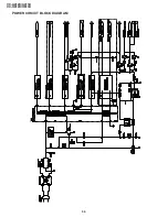
Страница 53: ...56 VC A412U A413U VC H812U H813U POWER CIRCUIT BLOCK DIAGRAM ...
Страница 63: ...72 VC A412U A413U VC H812U H813U M E M O ...


