44
VC-A412U/A413U
VC-H812U/H813U
1
2
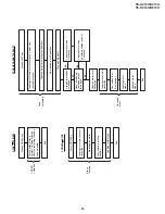
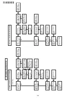
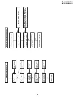
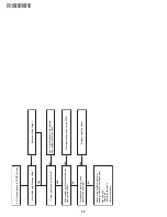
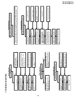
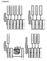
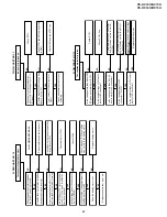
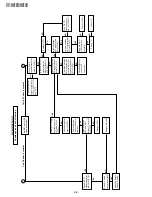
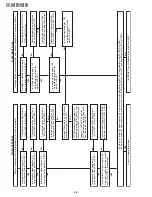
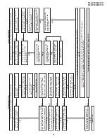
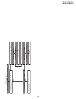
FLOW CHART NO.17
Capstan servo does not function.
Only PB mode inoperative
YES
Only REC mode inoperative
YES
YES
NO
YES
NO
NO
NO
NO
NO
Check peripheral
circuit of pin(50) of
IC701, C770, C771
and R770.
Is there 14.318MHz
oscillation at pins
(37) and (38) of
IC701?
Check peripheral
circuit of X701.
YES
YES
Does pin(29) of
IC701 operate
normally?
Check "
1
"
Check "
2
"
Check capstan
motor unit and/or
replace.
Is there capstan
AFC and APC
at pins(31) and (33)
of IC701?
Replace IC701.
Replace A/C head.
YES
YES
YES
NO
NO
NO
Is there capstan
AFC signal at pin
(31) of IC701?
NO
NO
NO
Is there capstan
APC signal at pin
(33) of IC701?
YES
NO
Replace IC701.
Does PB CTL
signal appear at
pin (76) of IC701?
Replace IC701.
Is there REC CTL
signal output at
pins(75) and (74)
of IC701?
Does PB CTL
signal appear at
pin(76) of IC701?
Does A/C head
operate normally?
Adjust the height
of the A/C head.
Does the capstan
FG signal appear
at pin (67) of IC-
701?
Check the capstan
FG signal line bet-
ween pin(6) of AC
connector and pin
(67) of IC701.
Check peripheral
circuit of AC
connector.
Is the V-SYNC
signal(reference) at
pin(50) of IC701?
Are REC and/or PB
mode inoperative?
Содержание VC-A412U
Страница 6: ...6 VC A412U A413U VC H812U H813U 1 3 LOCATION OF MAJOR COMPONENTS AND CONTROL ...
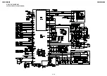
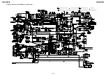
Страница 50: ...VC A412U A413U VC H812U H813U VC A412U A413U VC H812U H813U 50 51 8 BLOCK DIAGRAM SYSTEM SERVO BLOCK DIAGRAM ...
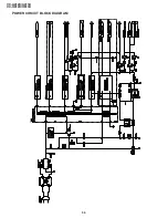
Страница 53: ...56 VC A412U A413U VC H812U H813U POWER CIRCUIT BLOCK DIAGRAM ...
Страница 63: ...72 VC A412U A413U VC H812U H813U M E M O ...

