


27
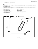
VC-A412U/A413U
VC-H812U/H813U
1
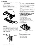
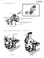
Insert Reverse Guide Lever Ass’y
Figure 4-41-1.
Figure 4-41-3.
Figure 4-41-2.
Phase Matching Point
2
Pinch Roller Double
Action Lever Ass'y
Open lever
2
Insert Pinch Roller/Pinch Double Action Lever Ass’y.
3
Insert Open Lever.
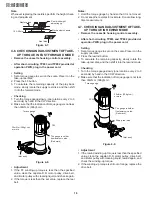
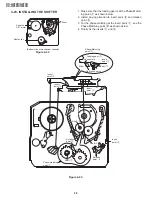
Insert reverse guide lever ass'y
Align here.
2
Insert pinch drive cam
Pinch drive lever ass'y
Fit the pinch drive cam so that the notch of pinch
drive cam aligns with the dent of pinch drive lever
assembly.
Fit the pinch drive cam so that the notch of
pinch drive lever assembly aligns with the
half-round notch of chassis.
Turn the reverse guide lever
assembly counterclockwise
to the stopper.
Содержание VC-A412U
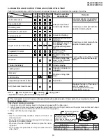
Страница 6: ...6 VC A412U A413U VC H812U H813U 1 3 LOCATION OF MAJOR COMPONENTS AND CONTROL ...
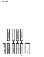
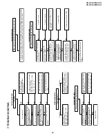
Страница 50: ...VC A412U A413U VC H812U H813U VC A412U A413U VC H812U H813U 50 51 8 BLOCK DIAGRAM SYSTEM SERVO BLOCK DIAGRAM ...
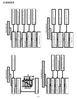
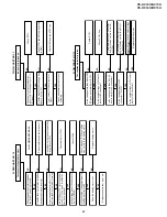
Страница 53: ...56 VC A412U A413U VC H812U H813U POWER CIRCUIT BLOCK DIAGRAM ...
Страница 63: ...72 VC A412U A413U VC H812U H813U M E M O ...


