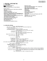


19
VC-A412U/A413U
VC-H812U/H813U
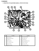
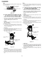
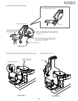
2. Visually check to see if the right edge of the tension pole
is within the 2.3
±
0.25 from the right edge of the Sup
guide shaft.
Insert the slotted screwdriver in the tension pole adjuster,
and rotate clockwise.
Figure 4-17.
At left side from the center line
Figure 4-15.
Figure 4-16.
Insert the slotted screwdriver in the tension pole adjuster,
and rotate counterclockwise.
At right side from the center line
Tension pole adjuster adjusting range
2.3
±
0.25
2.3
±
0.25
2.3
±
0.25
Sup guide shaft
Adjust so that the delta mark of tension pole adjuster is
within 90
°
range (left, right).
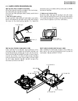
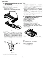
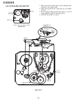
4-13. CHECKING AND ADJUSTMENT OF
RECORD/PLAYBACK BACK TENSION
•
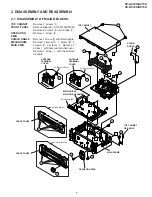
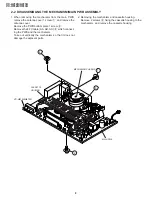
Remove the cassette housing control assembly.
•
After short-circuiting TP803 and TP802 provided at
operation PWB, plug in the power cord.
•
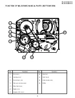
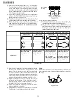
Setting
1. Turn off the power switch.
2. Open the torque cassette meter and fix with tape.
3. Set the cassette tape in loading state.
4. Put the weight (500g) on the cassette torque meter.
5. Turn on the power switch.
Make the adjustment with the beginning of a T-120 tape.
Tension pole adjuster
90
°
90
°
Figure 4-18.
Tension pole
500g
Weight to prevent
float (500g)
Cassette torque
meter
Figure 4-19.
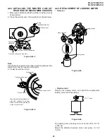
•
Checking
1. Push the REC button to place the unit in the SP record
mode.
2. At this time ascertain that the back tension is within the
setting (36.5 to 52g·cm) by seeing the indication of
torque cassette meter.
Содержание VC-A412U
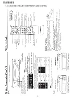
Страница 6: ...6 VC A412U A413U VC H812U H813U 1 3 LOCATION OF MAJOR COMPONENTS AND CONTROL ...
Страница 50: ...VC A412U A413U VC H812U H813U VC A412U A413U VC H812U H813U 50 51 8 BLOCK DIAGRAM SYSTEM SERVO BLOCK DIAGRAM ...
Страница 53: ...56 VC A412U A413U VC H812U H813U POWER CIRCUIT BLOCK DIAGRAM ...
Страница 63: ...72 VC A412U A413U VC H812U H813U M E M O ...


