background image

CHAPTER 1. OUTLINE OF THE PRODUCT

PN-T321/T322B 

OUTLINE OF THE PRODUCT

 1 – 11

3. SCREEN DISPLAY

3 - 1. SWITCHING THE SCREEN SIZE

Even when the screen size is changed, the display may remain the same depending on the input signal.

MEMO

n

Using this monitor’s screen-size switching or dual-screen display functions to compress or expand the screen for commercial or public viewing
in establishments like cafes or hotels may infringe on the rights of the creators, as protected by Copyright Law, so please be careful.

n

The appearance of the original video may change if you select a screen size with a different aspect ratio than the original image (e.g. TV broad-

cast or video input from external equipment).

n

When an ordinary non-wide image (4:3) is viewed with the whole screen using the screen-size switching function of this monitor, the edge of

the image may be lost or appear distorted. If you wish to respect the creator’s intentions, set the screen size to “NORMAL”.

n

When playing commercial software, parts of the image (like subtitles) may be cropped. In this case select the optimal screen size using the
screen-size switching function of this monitor. With some software, there may be noise or distortion at the edges of the screen. This is due to

the characteristics of the software, and is not a malfunction.

n

Depending on the original image size, black bands may remain at the edges of the screen.

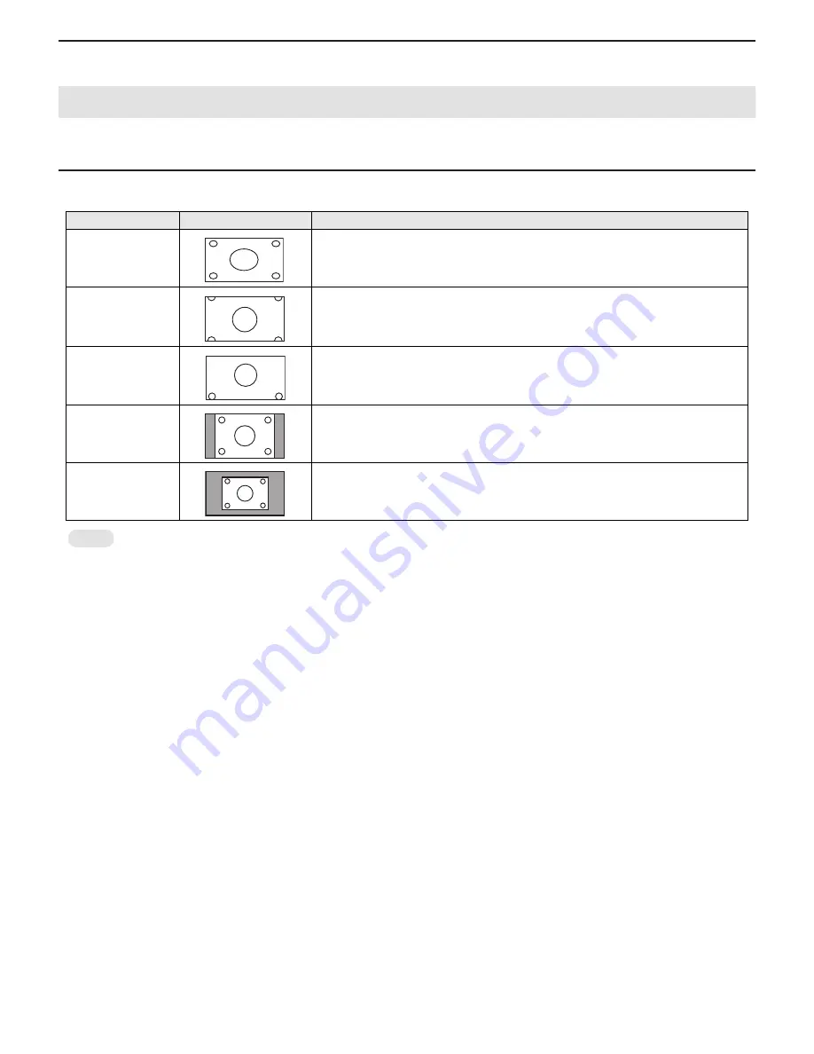
Mode

Screen display

PC input

WIDE

Displays image so it fills the entire screen.

ZOOM 1

An image with a 4:3 aspect ratio is enlarged to fill the entire screen without changing the 

aspect ratio. The edges of the image may be cut off.

ZOOM 2

Use this size if ZOOM 1 cuts off the subtitles.

NORMAL

Displays image so it fills the screen without changing the aspect ratio of the input signals.

Dot by Dot

Displays the dots of the signals input from the connected PC as the corresponding dots on 
the screen.

Содержание PN-T321

Страница 1: ...ice PNT321SME2 LCD MONITOR TOUCH PANEL INTEGRATED DISPLAY PN T321 MODEL PN T322B LEAD FREE SOLDER CHAPTER 1 OUTLINE OF THE PRODUCT 1 1 CHAPTER 2 INSTALLATION ADJUSTMENT SETTING 2 1 CHAPTER 3 CONTROLLING THE MONITOR WITH A PC 3 1 CHAPTER 4 IMPORTANT INFORMATION FOR SERVICING THE DISPLAY 4 1 CHAPTER 5 SERVICE MENU VARIOUS SETTING TOOL OPERATING PROCEDURES 5 1 CHAPTER 6 FIRMWARE UPDATA PROCEDURES EDI...

Страница 2: ... PERATING PROCEDURES Of TOUCH PANEL INSPECTION TOOL 5 8 CHAPTER 6 FIRMWARE UPDATA PROCEDURES EDID WRIT ING PROCEDURES 1 MAIN FIRMWARE UPDATE PROCEDURE 6 1 2 EDID WRITING PROCEDURES 6 2 CHAPTER 7 DISASSEMBLY AND ASSEMBLY 1 PWB AND WIRING DIAGRAM 7 1 2 REAR COVER 7 3 3 SPEAKER UNIT 7 4 4 LED DRIVER PWB 7 5 5 INLET HARNESS AC SWITCH 7 6 6 POWER SUPPLY PWB 7 8 7 TEMPERATURE SENSOR PWB 7 8 8 I F PWB 7 ...

Страница 3: ...ii CHAPTER 9 HARDWARE DESCRIPTIONS 1 SYSTEM DESCRIPTION 9 1 2 FUNCTIONS 9 3 3 PERFORMANCE SPECIFICATIONS 9 3 4 BLOCK DIAGRAM 9 4 5 TOUCH PANEL PN T322B 9 5 ...

Страница 4: ...he exclusive use solder ing iron is recommendable When repairing a lead free solder PWB use lead free solder thread Never use conventional lead solder thread which may cause a breakdown or anaccident Example LEAD FREE SOLDER The battery supplied with this product contains traces of Lead For EU For Switzerland The used battery is to be returned to the selling point For other non EU countries Please...

Страница 5: ...Digital HDMI x 1 DVI D 24 pin HDCP compatible x 1 Analog Mini D SUB 15 pin 3 rows x 1 Composite video RCA pin x 1 1 Component RCA pin Y Cb Pb Cr Pr x 1 2 Audio 3 5mm mini stereo jack x 1 RCA pin L R x 1 1 Serial RS 232C D SUB 9 pin x 1 USB flash drive x 1 for slideshow Output terminal Audio 3 5mm mini stereo jack x 1 Speaker output 8 W 8 W Touch Panel Detection method Infrared camera method Detect...

Страница 6: ...be some deviations from these values in individual units 1 2 DIMENSIONAL DRAWINGS Note that the values shown are approximate values 1 When mounting the monitor be sure to use a wall mount bracket that complies with the VESA compatible mounting method SHARP recommends using M6 screws and tighten the screws Note that screw hole depth of the monitor is 3 8 inch 10mm Loose mounting may cause the produ...

Страница 7: ...z Yes Yes Yes 56 5kHz 70Hz 75 0MHz Yes Yes Yes 60 0kHz 75Hz 78 75MHz Yes Yes Yes 1152 x 864 1 67 5kHz 75Hz 108 0MHz Yes Yes Yes 1280 x 768 47 8kHz 60Hz 79 5MHz Yes Yes 60 3kHz 75Hz 102 25MHz Yes Yes 1280 x 800 1 49 7kHz 60Hz 83 5MHz Yes Yes Yes 1280 x 960 1 60 0kHz 60Hz 108 0MHz Yes Yes Yes 1280 x 1024 1 64 0kHz 60Hz 108 0MHz Yes Yes Yes 80 0kHz 75Hz 135 0MHz Yes Yes Yes 1360 x 768 47 7kHz 60Hz 85...

Страница 8: ...d 1 n Conversion cable for AV component 1 green blue red n Conversion cable for AV video 1 red white yellow n CD ROM Utility Disk for Windows 1 Sharp Corporation holds authorship rights to the Utility Disk pro gram Do not reproduce it without permission n Setup Manual 1 n Vertical sticker Operation panel 1 n Vertical sticker Logo 1 n USB flash drive cover 1 n USB flash drive cover screw 1 PN T321 ...

Страница 9: ...MDS clock No Function No Function 1 N C 6 N C 2 Transmitted data 7 N C 3 Received data 8 N C 4 N C 9 N C 5 GND DVI D 24 PIN D SUB 9 PIN No Function No Function 1 Red video signal input 9 5V 2 Green video signal input 10 GND 3 Blue video signal input 11 N C 4 N C 12 DDC data 5 GND 13 Hsync signal input 6 GND for red video signal 14 Vsync signal input 7 GND for green video signal 15 DDC clock 8 GND ...

Страница 10: ...lashing in red3green3red3green at 1 second intervals Temperature abnomaly The message TEMPERATURE blinks at 5 second intervals in the corner of the screen Lower left corner at the fac tory default and it indicates an abnormality in the internal temperature It operates only when FUNCTION TEMPERATURE ALERT is set to OSD LED or LED When it is OFF it does not blink Factory default LED Even when FUNCTI...

Страница 11: ... the sound If you do not press any buttons for about 4 sec onds the VOLUME menu automatically disap pears BRIGHT buttons Pressing or displays the BRIGHT menu when the menu screen is not displayed Press or to adjust the brightness If you do not press any buttons for about 4 sec onds the BRIGHT menu automatically disap pears Cursor control buttons 5 DISPLAY button Displays monitor information When y...

Страница 12: ...he remote control unit to liquids and do not place it in an area with high humidity n The remote control unit may not work properly if the remote con trol sensor is under direct sunlight or strong lighting n Objects between the remote control unit and the remote control sensor may prevent proper operation n Replace the batteries when they run low as this may shorten the remote control s operation ...

Страница 13: ...n as double clicking a mouse Quickly touch twice Be sure to lift your finger sufficiently off the screen after the first tap If there is insufficient distance between the screenand your finger dou ble tap will not take place DRAG AND DROP Same action as drag and drop with a mouse Touch the screen with your finger and move without lifting When you have finished the movement lift your finger FLICKS ...

Страница 14: ...e point touched The left right buttons of the image can be clicked to perform the same actions as left right clicking a mouse INPUT PANEL A software keyboard and an input panel with handwriting recognition appear on the screen In Windows 7 excluding Starter the ink function of Microsoft Office can be used Handwritten comments can be written and handwriting can be recog nized 3For details see Micro...

Страница 15: ...mage may be lost or appear distorted If you wish to respect the creator s intentions set the screen size to NORMAL n When playing commercial software parts of the image like subtitles may be cropped In this case select the optimal screen size using the screen size switching function of this monitor With some software there may be noise or distortion at the edges of the screen This is due to the ch...

Страница 16: ...n the above range n Temperature condition may change when using the display together with the optional equipments recommended by SHARP In such cases please check the temperature condition specified by the optional equipments n Adhere to the following when installing the monitor in its vertical orientation Failing to adhere to the following may cause malfunc tions Install the monitor such that the ...

Страница 17: ...l 1 USB Video input PC AV HDMI input terminal n Use a commercially available HDMI cable conforming to the HDMI standard n If connecting by HDMI cable connection to the audio input terminal is unnecessary n If audio will not be input using an HDMI cable connect the audio to the PC audio input terminal PC D SUB input terminal n Connect using a commercially available signal cable Mini D SUB 15 pin Au...

Страница 18: ... PC s COM port RS 232C connector and the RS 232C input terminal on the monitor COMMUNICATION CONDITIONS Set the RS 232C communication settings on the PC to match the moni tor s communication settings as follows 1 2 CONNECTING THE POWER CORD CAUTION n Do not use a power cord other than the one supplied with the monitor 1 Turn off the main power switch 2 Plug the power cord supplied into the AC inpu...

Страница 19: ...crew Insert the claw 1 into the monitor and while pressing in the direc tion of 2 insert the claw 3 into the monitor MEMO n If the USB flash drive will be attached use a USB flash drive with dimensions no greater than 3 1 8 inch 80mm L x 15 16 inch 25mm W x 7 16 inch 12mm H n To remove the USB flash drive cover reverse the procedure Using excessive force may break the claws Exercise caution CAUTIO...

Страница 20: ...ing is 65 000 col ors the color levels in the color pattern may appear differently or grayscale may appear to be colored This is due to the specifications of the input signal and is not a malfunction 2 1 AUTOMATIC ADJUSTMENT When you use the PC D SUB input terminal to display a PC screen for the first time or when you change the setting of the PC use the auto matic screen adjustment 1 Switch the i...

Страница 21: ...T AV signal input 0 60 D AV D D D AV D COLORS AV signal input 0 60 D AV D D D AV D SHARPNESS AV signal input 0 7 D AV D D D AV D NOISE REDUCTION AV signal input LOW MIDDLE HIGH D AV D D D AV D COLOR MODE STD VIVID sRGB As shown in the left column sRGB is D SUB and DVI D only D D D D D D WHITE BALANCE COOL STD WARM As shown in the left column D D D D D D USER R CON TRAST 0 255 D D D D D D G CON TRA...

Страница 22: ...8 x 480 As shown in the left column D 768 LINES AUTO 1024 x 768 1280 x 768 1360 x 768 1366 x 768 As shown in the left column D 1050 LINES 1400 x 1050 1680 x 1050 As shown in the left column D USB EFFECT WIPE TOP WIPE BOTTOM WIPE LEFT WIPE RIGHT DIAGONAL WIPE LEFT TOP DIAGONAL WIPE RIGHT TOP DIAGONAL WIPE LEFT BOTTOM DIAGONAL WIPE RIGHT BOTTOM EXTEND FROM CENTER H EXTEND FROM CENTER V COMPRESS TO C...

Страница 23: ...S AV signal input 30 SHARPNESS AV signal input 4 NOISE REDUCTION AV signal input MIDDLE COLOR MODE STD VIVID sRGB STD WHITE BALANCE COOL STD WARM STD USER R CONTRAST 255 G CON TRAST 255 B CONTRAST 255 AUDIO TREBLE 0 BASS 0 BALANCE 0 SETUP THERMAL SENSOR SETTING LANDSCAPE PORTRAIT LANDSCAPE LANGUAGE ENGLISH OPTION COLOR SYSTEM AUTO AUDIO OUTPUT VARIABLE1 VARIABLE2 FIXED VARIABLE1 INPUT SIGNAL D SUB...

Страница 24: ...st with e and d Adjust with e and d Adjust with e and d Adjust with e and d Adjust with e and d Adjust with e and d Initialize with d d OPTION COLOR SYSTEM AUDIO OUTPUT INPUT SIGNAL c d USB EFFECT INTERVAL LIST c d SETUP THERMAL SENSOR SETTING LANGUAGE c Adjust with e and d Adjust with e and d Adjust with e and d Adjust with e and d Adjust with e and d Adjust with e and d Adjust with e and d Adjus...

Страница 25: ...nnect the USB cable for the touch panel to the PC 4 Insert the supplied CD ROM into the CD ROM drive of your PC 5 Open the CD ROM drive in Computer or My Computer 6 Double click the TouchPanel folder 7 Double click NextWindow_2500_Driver_xxxx_Generic exe Touch Panel Driver MEMO n xxxx shows the version 8 Click Next Follow the on screen instructions to install the touch panel driver n When the User...

Страница 26: ... Touch Screen Calibration Utility 3 Click OK SETTINGS AND TOOLS TAB USER TOUCH PREFERENCE TAB 1 Calibrate Adjust positioning so that the mouse cursor correctly moves to the position touched on the screen Click Calibrate to open the settings Follow the on screen instructions n Touch until the crosshair moves to the next position n To cancel during calibration press the ESC key on the keyboard 2 Set...

Страница 27: ...ick Programs and Features n In Windows XP click Add or Remove Programs In the Clas sic View double click Add or Remove Programs 5 In Windows XP Vista remove Touch Screen Calibration Utility This step is not necessary in Windows 7 Go to step 6 Follow the on screen instructions n When the User Account Control screen appears click Yes or Allow 6 Remove NextWindow 2500 Drivers Touch Panel Driver Follo...

Страница 28: ... according to the received command and sends a response mes sage to the PC If a command has R listed for DIRECTION in the RS 232C com mand table the current value can be returned by using as the parameter Baud rate 9600bps Data length 8 bits Parity bit None Stop bit 1 bit Flow control None Return code Command field 4 prescribed alphanumerical characters Parameter field 4 character string comprised...

Страница 29: ...f you wait a while Do not send any command during this period COMMANDS WHICH RETURN WAIT When one of the following commands is used RSET INPS ASNC WIDE POWR WHEN CONTROL VIA RS 232C IS LOCKED TO PREVENT USE USING THE OPERATION LOCK FUNCTION COMMUNICATION INTERVAL n After OK or ERR is returned you must send the following commands To set a timeout for the command response specify 10 seconds or longe...

Страница 30: ...used in power standby mode Function Command Direction Paramete Reply Control Response contents 1 POWER CONTROL POWR W 0 Switches to standby mode 1 Returns from standby mode R 0 Standby mode 1 Normal mode 2 Input signal waiting mode INPUT MODE SELECTION INPS W 0 Toggle change for input mode 1 DVI D 2 D SUB 3 COMPONENT 4 VIDEO 9 HDMI 11 USB R 1 DVI D 2 D SUB 3 COMPONENT 4 VIDEO 9 HDMI 11 USB Functio...

Страница 31: ...Value BRIGHT VLMP WR 0 31 0 31 TEMPERATURE SENSOR DSTA R 0 Internal temperature normal 1 Internal temperature abnormal Standby mode 2 Internal temperature abnormal Temperature is normal now but it was abnormal during operation 3 Internal temperature abnormal Brightness of the backlight decreases 4 Temperature sensor abnormal TEMPERATURE ACQUISI TION ERRT R Value Temperature at temperature sensors ...

Страница 32: ... EDID written in it If necessary the EDID should be updated to the latest 3Refer to page 6 2 2 EDID WRITING PROCEDURES 4 Each service part has the firmware written in it If necessary the firmware should be updated to the latest 3Refer to page 6 1 1 MAIN FIRMWARE UPDATE PROCEDURE 5 Write the information read in the above step 1 MEMO n When the reading cannot be executed conduct the following operat...

Страница 33: ...H PANEL 1 Execute the touch panel inspection and perform calibration 3Refer to page 5 8 10 PERATING PROCEDURES Of TOUCH PANEL INSPECTION TOOL 1 5 SERVICE TOOL COMPARISON TABLE SERVICE TOOL PN T321 T322B PN 325 Previous Model PN V601 Reference WHITE BALANCE SETTING TOOL SERIAL NUMBER SETTING TOOL USAGE TIME SETTING TOOL MODEL NAME SETTING TOOL TEMPERATURE MONITOR SETTING TOOL THE LOG TOOL INITIALIZ...

Страница 34: ...r FIRM VERSION Firmware version USAGE TIME Time while the display is in use SERVICE1 SERVICE2 DVI D END MENU NO SIGNAL MODEL MODEL TYPE S N FIRM VERSION USAGE TIME PN TXXX JP XXXXXXXXXX Ver 1 00 62H AGING AGING 3Refer to page 5 2 2 AGING FACTORY RESET Used to reset the user adjustment values the usage time and the operation logs to the factory setting 3Refer to page 5 2 3 FACTORY RESET EDID WRITE ...

Страница 35: ... when no input signal is received Even if you are performing AGING1 or AGING2 when there is any input signal received it displays not the aging screen but the input signal After that once the input signal goes out the aging screen is displayed again MEMO n The power button of the remote controller cannot terminate aging 3 FACTORY RESET Resets the user adjustment value USAGE TIME and the Operation ...

Страница 36: ...and line option syntax error Type Command for Help is displayed the user name may contain some 2 byte char acters Japanese Log in with the user name of 1 byte characters English having administrative right and install it If there is no user name created newly create a user name through the User Account in the Control Panel USE INSTRUCTIONS 1 Execute ServiceToolsLauncher exe in the folder where the...

Страница 37: ...s Serial Number button of the Service Tool Launcher 7 3 SERIAL NUMBER SETTING PRO CEDURES The procedures of setting serial numbers with use of the Serial Number Setting Tool are as follows 1 Press Connection Setting button to configure the communica tion settings 2 Input the serial number you need to set in the field of Write Data 3 Press Write button 4 Press Read button and confirm that the set s...

Страница 38: ...et ting Tool are as follows 1 Press Connection Setting button to configure the communica tion settings 2 Input the usage time you need to set in the field of Write Data It should be from 000000 to 200000 Make sure to input a 6 digit number 3 Press Write button 4 Press Read button and confirm that the set usage time is dis played in the Read Data field 8 4 USAGE TIME CHECK PROCEDURE With an image d...

Страница 39: ...HERMAL SENSOR SETTING of the SETUP menu is set to LANDSCAPE After operating the tool be sure to reset THERMAL SENSOR SETTING to the proper setting When the temperature watch setting information needs to be retrieved read out the setting data by following the procedures below 9 2 START UP OF THE TEMPERA TURE WATCH SETTING TOOL 1 Press Temp Watch button of the Service Tool Launcher screen 9 3 READ O...

Страница 40: ...atch setting data contains a part that stores the usage time of the display as basic information 1 Press Reset button to execute the reset 2 To confirm that the settings have been properly reset press Read button to read out the set values 3 For the default settings please see the followings DEFAULT THRESHOLD TEMPERATURE PN T321 PN T322B Installation Orientation Landscape installation Portrait ins...

Страница 41: ...splayed as shown below so you need to click Yes Folder not found message is displayed only for the first time Click OK 2 After USB Settings Lite is launched press appropriate buttons and inspect a touch panel Buttons Explanation Pixel Map Aperture Auto Cam Draw Test Finalise Initial setting and inspection of a touch panel These commands are done continuously Press any button then the remaining com...

Страница 42: ...sary After it is finished the next inspection starts automatically The next inspection sometimes doesn t start without any error caution In this case click Pixel Map button again 3 APERTURE The following screen is displayed Yellow circles are displayed Touch the corner of the screen by a pen until these circles completely becomes green Follow the instruction and touch the corner 1left top3 2right ...

Страница 43: ...If a red line is still displayed an installation of a camera unit or a reflection frame might not be proper or a camera unit might have any problem Whether doing compensation or not if all the lines becomes green press F2 key and do compensation 4 point calibration and drawing 9 lines once again DRAWING 4 CORNERS Next draw lines along the yellow L shaped part displayed at the left right bottom of ...

Страница 44: ...d 7 digits serial number format like as 2500 nnnnnnn 5 Select File Open from the menu bar A file selection window is displayed then open nnnnnnn v551 nnnnnnn is the serial number file saved in Step1 After all above step are done inspect again from PixelMap 10 3 WAVEFORM OF THE AMOUNT OF LIGHT After the inspection is done the waveform normally becomes like as above Red waveform is camera unit 1s Ca...

Страница 45: ...d above into the USB terminal of the rear side of the display 2 Set the input mode to USB the message is displayed as shown below Then press the DISPLAY button of the remote control 3 The updating process starts and the following screen is displayed CAUTION n Do not turn off the power during the updating process And do not pull the USB memory Otherwise the system won t be restored 4 When the updat...

Страница 46: ... The window for checking the execution content is displayed If it is OK press YES and if not press NO n When YES is pressed the process goes on to the next step n When NO is pressed the display returns to 3 5 When the following window is displayed connect the monitor to the jig SETTING ON THE MONITOR SIDE Connect the VGA cable and the DVI HDMI cable to the monitor and the jig 3Refer to page 6 6 VG...

Страница 47: ...to the monitor and the jig 3Refer to page 6 6 DVI Cancel write protect of EDID Refer to 5 to cancel write protect of EDID 11 Click Start button 12 The window below is displayed On the above screen EDID is written and verified If the operation is interrupted before completion the connection may be improper Check for it After completion of writing click Finish button 13 In case of an error occurs in...

Страница 48: ...t Current configuration If I O range is already 0378 037F there is no need to change FOR Windows Vista Windows 7 1 Open the system of the Control Panel 2 Open the System and Maintenance and click the Device Manager 3 Click the Continue button in User Account Control Dialog 4 Click mark on the left of Port COM LPT Check to confirm that there is ECP printer port LPT1 5 Open the property of the print...

Страница 49: ...e 1 Execute START Program Accessory Communication Hyper terminal The window below is displayed Enter an optional name and press OK 2 The window below is displayed Select the number of COM con nected to the monitor and press OK 3 The communication setting screen is displayed Set as shown below 4 Set the local echo Select Property in the file menu 5 Select Settings tab and press ASCII Setup 6 Check ...

Страница 50: ...le No need to connect the serial cable DVI D connector SW1 SW2 SW3 SW4 Jig PWB X1049MP 27 Left right right right with the parallel connector on the upper side DVI HDMI cable HDMI terminal DVI terminal DIP switch setting Parallel EDID Serial PROGRAM AUTO MANUAL 1502A T1620 1502A T1620 Body rear VGA terminal Connect to USB port of PC Connect to printer port of PC VGA USB Serial connector Parallel co...

Страница 51: ...ING DIAGRAM PN T321 5 10 1 A B C D E 8 9 6 7 3 2 4 No Parts name Parts code A LED driver PWB 0QP0000000036 B Power supply PWB 0QP0000000035 C Temperature sensor PWB 0QP0000000037 D Main PWB 0QP0000000034 E Key PWB 0QP0000000038 No Cable name Parts code 1 LED driver PWB cable 0QP0000000021 2 LCD module cable 0QP0000000020 3 Speaker L cable 0QP0000000025 4 Speaker R cable 0QP0000000024 5 Key FFC 0QP...

Страница 52: ...000015 E Key PWB 0QP0000000038 F Touch panel assembly DUNT 1854MPZZ No Cable name Parts code 1 LED driver PWB cable 0QP0000000021 2 LCD module cable 0QP0000000020 3 Speaker L cable 0QP0000000025 4 Speaker R cable 0QP0000000024 5 Key FFC 0QP0000000023 6 Power supply harness 0QP0000000022 7 Temperature watch control cable 0QP0000000029 8 AMP power supply cable 0QP0000000026 9 AC power supply Inlet c...

Страница 53: ... 8 silver Unscrew 6pcs of screw C 3 x 6 silver and 2pcs of screw D 3 x 4 silver and then remove the Rear Cover CAUTION n In the PN T322B be careful of the USB cable when removing the rear cover SCREW TIGHTENING TORQUE n Screw A B 0 7 0 9N m n Screw C 0 5 0 6N m n Screw D 2 5 3 5N m reference A Screw x 6 B Screw x 7 C Screw x 6 D Screw x 2 USB cable PN T322B ...

Страница 54: ...connect 2 connectors and cut 3 points of the binding band 2 Unscrew 4pcs of screws 3 x 10 black and remove the fixing tape of the harness Remove the Speaker Unit CAUTION SCREW TIGHTENING TORQUE n 0 167 0 196N m Fixing tape of the harness Screw x 4 2 connectors Red Black White Black Binding band x 3 ...

Страница 55: ...HTENING TORQUE n 0 7 0 9N m 2 Disconnect 4 connectors from the LED drive PWB 3 Unscrew 4pcs of screws 3 x 6 silver and remove the LED driver PWB Remove the harness from the saddle CAUTION NOTE FOR DISASSEMBLY n As the harness is directly connected to the LCD module be careful not to have the wire broken when removing SCREW TIGHTENING TORQUE n 0 167 0 196N m Connector Screw x 4 4 connectors Screw x...

Страница 56: ...1 Disconnect 1connector and remove the cable band 2 Unscrew 2pcs of screw A 3 x 6 silver and remove the plate Unscrew 2pcs of screw B 3 x 6 silver and remove the AC inlet AC switch assy CAUTION SCREW TIGHTENING TORQUE n 0 5 0 6N m A B AC inlet AC switch assy Cable band Screw x 2 Screw x 2 Connector Plate ...

Страница 57: ...witch Unscrew 2pcs of screw A 3 x 6 black and 1pc of screw B 4 x 8 silver Remove the inlet harness CAUTION SCREW TIGHTENING TORQUE n Screw A 0 118 0 176N m n Screw B 0 26 0 32N m A B 4 connectors Screw x 2 Screw x 1 AC switch Black AC inlet harness Red Confirm that the circle is on the right side and it is in the OFF state ...

Страница 58: ...ews 3 x 6 silver and then remove the power supply PWB CAUTION SCREW TIGHTENING TORQUE n 0 118 0 176N m 7 TEMPERATURE SENSOR PWB 1 Disconnect the connector of the temperature sensor PWB Unscrew 1pc of screw 3 x 6 silver and remove the temperature sensor PWB CAUTION SCREW TIGHTENING TORQUE n 0 167 0 196N m 3 connectors Screw x 2 Connecter Screw ...

Страница 59: ... remove the angle Unscrew 2pcs of screw B 3 x 6 silver and remove the plate CAUTION NOTE FOR ASSEMBLY n Make sure that the ground terminals are attached horizontally as shown in the illustration SCREW TIGHTENING TORQUE n 0 5 0 6N m B A The orientation of the ground terminals is as shown in the illustration Screw x 4 Screw x 2 Plate Angle ...

Страница 60: ... screws 3 x 6 silver Remove the I F PWB assy together with the aluminum tape CAUTION SCREW TIGHTENING TORQUE n 0 5 0 6N m 3 Unscrew 6pcs of hexagonal screws and remove the I F PWB CAUTION SCREW TIGHTENING TORQUE n 0 35 0 45N m FFC Lock release 6 connectors Screw x 4 Aluminum tape I F PWB assy Hexagonal screw x 6 I F PWB ...

Страница 61: ...ing plate and the USB cable Remove two screws D 3 x 6 Silver and remove the plate CAUTION NOTE FOR ASSEMBLY n Make sure that the ground terminals are attached horizontally as shown in the illustration SCREW TIGHTENING TORQUE n Screw A 0 7 0 9N m n Screw B 0 5 0 6N m n Screw C D 0 5 0 6N m Angle Connectors Plate USB cable fixing plate C Screw A x 4 Screw B x 4 Screw D x 2 Screw The orientation of t...

Страница 62: ...he I F PWB assembly CAUTION n The touch panel PWB assembly is connected with the FFC If it is separated too far from the LCD module the FFC may be damaged SCREW TIGHTENING TORQUE n 0 5 0 6N m 3 Unscrew 6pcs of hexagonal screws and remove the I F PWB CAUTION SCREW TIGHTENING TORQUE n 0 35 0 45N m Touch panel PWB assy Lock release FFC 6 connectors Screw x 5 Aluminum tape I F PWB assy I F PWB Hexagon...

Страница 63: ...ew 2pcs of screw A 4 x 10 black Unscrew 4pcs of screw B 4 x 6 black and then remove the plate Unscrew 4pcs of screw C 4 x 10 black and remove 3 bezels Unscrew 6pcs of screw D 4 x 8 silver and remove the LCD module from the Front Cabinet CAUTION SCREW TIGHTENING TORQUE n 0 167 0 196N m B D A C Key FFC Fixing tape x 5 Bezel x 3 Screw x 6 Screw Plate x 2 Screw x 4 Screw x 4 ...

Страница 64: ... black Unscrew 4pcs of screw B 4 x 6 black and then remove the plate Unscrew 4pcs of screw C 4 x 10 black and remove 3 bezels and remove the LCD module from the Front Cabinet CAUTION SCREW TIGHTENING TORQUE n Screw A C 0 7 0 9N m n Screw B 0 5 0 6N m Screw x 4 B Screw x 2 A Screw x 4 C Slide in the arrow direction of the engraved mark to remove Plate Key FFC Bezel x 3 Fixing tape x 5 ...

Страница 65: ...B DISASSEMBLY AND ASSEMBLY 7 15 10 KEY PWB PN T321 1 Remove the tape Remove the key PWB Remove the FFC PN T322B 1 Remove the key PWB cover Remove the key PWB Remove the FFC Lock release Key PWB Tape FFC FFC FFC Key PWB cover FFC Lock release Key PWB ...

Страница 66: ...at three positions Turn over the display and remove the front cabinet from the machine 3Refer to page 7 5 4 LED DRIVER PWB CAUTION n When removing the front cabinet do not separate it from the machine excessively since the key PWB attached to the front cabinet is connected to the machine with the FFC Otherwise the FFC may be broken SCREW TIGHTENING TORQUE n Screw A B 0 5 0 6N m n Screw C 0 7 0 9N ...

Страница 67: ...embly 3Refer to page 7 8 6 POWER SUPPLY PWB CAUTION NOTE FOR ASSEMBLY n When assembling first attach the angle lower side and then attach the touch panel assembly and slide the angle upper side in the arrow direction to attach In addition do not stretch the FFC cable but allow slack and attach the fixing tape to the FFC SCREW TIGHTENING TORQUE n 0 7 0 9N m Fixing tape x 2 Angle Top side Angle Lowe...

Страница 68: ...N IS SHIFTED EVEN AFTER CALIBRATION 8 5 10 MULTI TOUCH IS UNABLE 8 6 Replace the abnormal part with a new one Replace the abnormal part with a new one No abnormality No abnormality Abnormality Abnormality Abnormality Replace the abnormal part with a new one Does the power PWB supply the power voltage of 5V 5V 12V 24V Is there any abnormality in the switch cable Is there any abnormality in the AC p...

Страница 69: ...re any abnormality in the connection cable Is there any abnormality in the I F PWB Is the adjustment locked is the button operation with the remote controller inhibited by the main unit Release the adjustment lock No abnormality No abnormality Replace the abnormal part with a new one Abnormality Is there any abnormality in the I F PWB Replace the abnormal part with a new one No abnormality Abnorma...

Страница 70: ...there any abnormality in the I F PWB and related sections Abnormality Is there any abnormality in the external speaker and related sections Is there any abnormality in the speaker cable Is there any abnormality in the speaker Replace the abnormal part with a new one No abnormality Abnormality Is there any abnormality in the audio input signal Is there any abnormality in the audio cable No abnormal...

Страница 71: ... installed on the program and function menu of the control panel Install the drivers Is the OS Windows7 Check the Pen and Touch on the control panel Is Finger is used as an input device in the touch tab checked Put a check mark Is Touch enable in the User Touch Environment Setting of RSCU checked Put a check mark Is NextWindow Low Rider Touch Screen displayed in Human Interface Devices of the devi...

Страница 72: ...rate Boot TSCU and perform calibration Yes Yes No No Yes Yes Yes Yes Yes No No No No No Is the unit installed in a place that is exposed to direct sunlight Change the installation site or installing direction Is the screen exposed to a strong illumination light Change the position of the illumination light or the direction of the set Is there any foreign material on the LCD surface Remove Is there...

Страница 73: ...mpliant with the multi touch function Is Multi touch gesture and ink are enable in the Touch tab of Pen and Touch on the control panel checked Non multi touch compliant Normal operation Put a check mark Check with a multi touch supporting application for example Microsoft Paint Replace the touch panel protection glass with the camera control PWB ...

Страница 74: ...a PWB unit for driving the LED backlight incorporated in the LCD unit INPUT ELECTRICAL CHARACTERISTICS LCD driving method Amorphous Silicon TFT Active Matrix Display pixel count 1366 x R G B x 768 pixel Pixel pitch sub pixel 0 17025 H x 0 51075 V mm Pixel array RGB vertical stripes Max display colors 16 7M color Contrast ratio 2500 1 Response speed 6 5ms gray to gray Screen display mode MVA Normal...

Страница 75: ...y LED Factory default n When it is set to OFF no notification is provided If the temperature is increasing further the display goes into standby mode In this case the LED inevitably blinks in red and green The description of abnormal temperature can be obtained through RS 232C Item Symbol Test Conditions Min Type Max Unit Output Current Max Iout Vin 24V Von 5V Vbrit 0V 600 mA Output Current Min Io...

Страница 76: ...ange of the operating temperature and humidity to the extent possible Baud rate 9600bps Data length 8bits Parity none Stop bit 1bit Flow control none Various settings Change of folders to be played inter val of image shift and effects Compliant format Still image JPEG Audio MP3 WMA Receiving distance 5 m Receiving scope 10 up to down left to right Ქ Ყ Ქ Ყ Light receiving section Light receiving se...

Страница 77: ...ce PWB unit USB RS232C Audio out A V in Component VGA DVI HDMI IR KEY LSI MT8223H DDR2 EEPROM FLASH SPEAKER AMP Speaker L Speaker R LED edge light PWB LCD Module 1366 x RGB x 768 dots 16 7M colors LED edge light PWB LED edge light PWB LCD drivers PWB LED Drive PWB unit Thermo sensor POWER SUPPLY PWB POWER SW AC inlet Power cable PC Audio ...

Страница 78: ... border to the left and eight sides and the lower side it is reflected in the same direc tion as the angle of incidence The line sensor in the camera unit detects reflected light in the range of about 90 At that time if the screen is touched with a finger etc reflection light at that section does not come back generating a shade DETECTION RANGE OF CAMERA UNIT 1 DETECTION RANGE OF CAMERA UNIT 2 3 T...

Страница 79: ...in the detected position TOUCH PANEL UNIT CONTROLLER PWB Provided at the back of the LCD module No Name 1 Controller PWB 2 Camera unit 1 3 Camera unit 2 4 Retroreflective border left side 5 Retroreflective border right side 6 Glass substrate 7 Retroreflective border Lower side Number of the Controller PWB side Number of the Camera unit side 1 2 4 6 7 3 5 No Name 1 USB cable 2 Controller PWB 3 FFC ...

Страница 80: ...ly Printed in Japan t COPYRIGHT 2011 BY SHARP CORPORATION All rights reserved Printed in Japan No part of this publication may be reproduced stored in a retrieval system or transmitted In any form or by any means electronic mechanical photocopying recording or otherwise without prior written permission of the publisher ...

Отзывы: