background image

MX-7000N  MX-PNX2A/B/C/D  6 – 1

MX-7000N

Service Manual


[6] MX-PNX2A/B/C/D

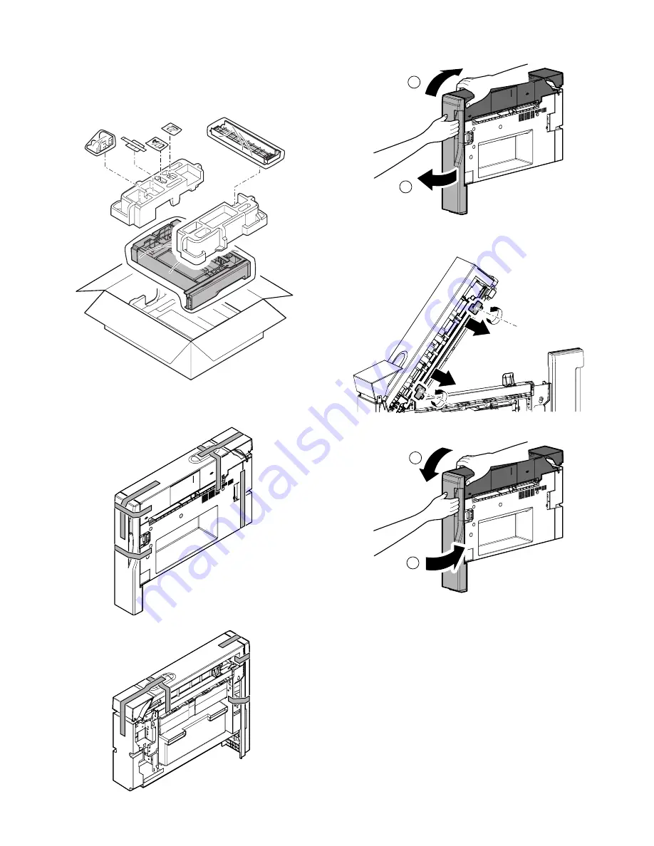
1. Unpacking

A. Pulling out of the punch unit

1)

Pull out the punch unit.

B. Removal of the protection material

1)

Remove the fixing tape and protection material.

2)

Open the front cover, and open the top cover.

3)

Remove the screws, and remove the fixing material. (2 posi-
tions)

4)

Close the top cover, and close the front cover.

1

2

1

2

Содержание MX 5500N - Color Laser - Copier

Страница 1: ...in unit 1 1 2 MX LCX2 Large capacity tray A4 2 1 3 MX LCX3 Large capacity tray A3 3 1 4 MX RBX2 Paper pass unit 4 1 5 MX CFX1 Inserter 5 1 6 MX PNX2A B C D Punch module 6 1 7 MX FNX3 4K finisher 7 1 8 MX FNX4 4K Saddle stitch finisher 8 1 9 MX FRX3 MX FRX3U Data security kit 9 1 10 MX PKX1 PS3 expansion kit 10 1 11 AR PF1 Barcode font kit 11 1 12 MX AMX1 Application integration module 12 1 13 MX F...

Страница 2: ...er MX FNX4 Finisher MX FNX3 Inserter MX CFX1 Punch module MX PNX2A B C D Paper pass unit MX RBX2 Staple cartridge Staple cartridge AR SC3 AR SC2 Large capacity tray A3 MX LCX3 Facsimile expansion kit MX FXX1 MX FWX1 MX AMX1 MX PKX1 Internet FAX expansion kit Sharpdesk license kit PS3 expansion kit AR PF1 Barcode font kit Application integration module MX USX1 5 MX US10 50 A0 Data security kit MX F...

Страница 3: ...he saddle stitch finisher is required When combining the finisher with the inserter the punch unit is required Finisher MX FNX3 Simultaneous installation with the saddle stitch finisher is inhibited Saddle stitch finisher MX FNX4 Simultaneous installation with the finisher is inhibited Punch module MX PNX2A Requires the finisher or the saddle stitch finisher and the paper pass unit MX PNX2B MX PNX...

Страница 4: ...of a step up transformer is also available In this case the capacity must be great enough for the max Power consumption of the machine 3 Power frequency waveform The frequency must be within the range of the specified frequency 2 If power waveform is deformed a trouble may occur 4 Safety Be sure to properly ground the machine 5 Power plug Check the form of the power plug If the shape does not matc...

Страница 5: ...It is recommendable to use a forklift for bringing in the machine for safety If no forklift is available Be sure to use the skid slope DKIT 0367FCZZ Be careful to safety and pull the machine down The carrying in must ensure manpower of four persons or more for safety The machine is considerably heavy and requires safety precautions for delivery and installation Transit of the machine must be made ...

Страница 6: ... main unit slightly and remove the bottom pad R 4 Lift the main unit slightly and remove the bottom pad L 5 Remove the vinyl bag from the main unit 6 Remove the slope Slope Deal as a parts 7 Attach the slope to the concave section of the skid Part name Part code Skid slope DKiT 0367FCZZ ...

Страница 7: ... Remove the fixing tape and protection material C Pulling out of the bundled items 1 Pull out the bundled items D Check the packed items 1 Check that all the items are included in the package NO Names of bundles Quantity 1 Waste toner bottle 1 2 Paper exit tray 1 3 Paper exit full detection actuator 1 4 Operation manual pocket 1 5 Operation manual 1 1 2 3 4 5 ...

Страница 8: ... plate fixing material and the tray note label Tray 1 tray 2 Tray 3 tray 4 2 Attach the removed fixing material to the position shown in the figure for storage B Fusing heat roller pressing 1 Release the lock and open the right door 2 Lower the pressure release lever to apply more pressure NOTE If the machine is left unused for one month or more the heat roller rubber may be deformed In such a cas...

Страница 9: ...sed as shown in A Failure to complete this step may damage the primary trans fer belt 3 Hold the drum fixing knob by the hand to not rotate remove the screw and remove the drum fixing knob 4 Pull out the fixing cover 5 Loosen the screws and open the cover of the process section 6 Release the fixing screw 1position for each color 7 Pinch the knob and remove the development unit 8 Remove two fixing ...

Страница 10: ...e developer use an extreme care not to drop developer on the drive section marked with 11 Install the DV cover in the arrow direction When installing the DV cover be sure to engage the pawls with the bosses 12 Fix the DV cover with the two screws 13 Shake the development unit horizontally a few times When supplying developer do not tilt the development unit A A A ...

Страница 11: ... the fixing screw D Infusing the developer black 1 Loosen the fixing screw 2 Hold the knob and remove the development unit 3 Remove the screws and remove the toner hopper unit 4 Disconnect the connectors on front side and rear side 5 While rotating the MG roller infuse the developer ...

Страница 12: ...de 7 Engage the pawls to the toner hopper unit and install it and fix with the screws 8 Shake the development unit horizontally a few times 9 Install the development unit 10 Fix with the fixing screw 11 Close the cover of the process section 12 Tighten the screws Push the fixing cover ...

Страница 13: ...y The following procedure are the installation procedures of the paper exit tray unit for North America and Australia New Zealand Because it is standard equipment for another destina tion the following procedure is unnecessary 1 Check the packed items 1 Check that all the items are included in the Package 2 Installation of the IL interface harness 1 Remove the screw and remove the switch cover No ...

Страница 14: ...re is possible However remove it for the working property 2 Install the paper exit tray Package part No 1 to the main unit and fix with the screws Package part No 5 3 Install the toner cover and fix it with a resin E ring 4 Installation of the paper holding arm and paper exit full detection actuator 1 Install the paper holding arm Package part No 2 and install the paper exit full detection actuato...

Страница 15: ...by pressing the CA key on the main unit ON ON ON M Y C K 0 AUTOMATIC DEVELOPER ADJUSTMENT EXECUTE AT DEVE ADJ_L_K 128 AT DEVEVO_L_Y 128 1 1 SIMULATION NO 25 02 TEST CLOSE AT DEVE ADJ_M_K 128 AT DEVE VO_M_Y 128 AT DEVE ADJ_L_C 128 AT DEVE VO_M_K 128 AT DEVE ADJ_L_M 128 AT DEVE VO_M_C 128 AT DEVE ADJ_L_Y 128 AT DEVE VO_M_M 128 AT DEVE ADJ_M_C 128 AT DEVE VO_H_K 128 AT DEVE ADJ_M_M 128 AT DEVE ADJ_M_...

Страница 16: ...d with the development unit removed be sure to remove the toner cartridge If not tone may be clogged Be sure to insert all of five toner cartridges Y M C BK1 BK2 Color toner cartridge positions 4 Insert the cartridge securely until it locks 5 Close the toner cover I Installation of the paper exit tray and the paper full detection actuator 1 Install the paper exit tray Package part No 2 and the pap...

Страница 17: ...hold the hooks and remove A4 size regulation plate LOGOUT LINE PRINT IMAGE SEND DA TA DA TA READY SYSTEM SETTINGS HOME JOB ST ATUS System Settings Admin Password Back Total Count Paper Tray Settings Printer Condition Settings Document Filing Control Address Control Fax Data Receive Forward USB Device Check Default Settings List Print User System Settings Paper Tray Settings Back Tray Settings Pape...

Страница 18: ...d base plate of the tray 1 gently hold the hooks and remove A4 size regulation plate Remove the sheet Double the sheet that have been removed and store it to the tray 2 3 Push down the paper feed base plate of the tray 2 gently hold the hooks and remove A4 size regulation plate Remove the sheet 4 Double the sheet that have been removed in step 2 and step 3 and install the A4 size regulation plate ...

Страница 19: ... the screw 7 Remove the screw and remove the mylar sheet Change the installing direction and install with screws 2 positions 8 Open the waste toner bottle section cover 9 Remove the B5 size regulation plate 10 Install the B5 size regulation plate to the tray 1 11 Attach the A4 size regulation plate to inner side of the waste toner bottle section cover 1 1 2 2 3 3 ...

Страница 20: ...ance Auto adjustment 5 Printer color balance Auto adjustment 1 Copy color balance adjustment Auto adjustment a Note before execution of the copy color balance adjust ment Auto adjustment Be sure to use the specified paper for color b Adjustment procedure 1 Enter the SIM 46 24 mode 2 Press EXECUTE key A3 or 11 x 17 paper is automatically selected The color patch image adjustment pattern is printed ...

Страница 21: ...e been completed properly Be sure to use the specified paper for color b Adjustment procedure 1 Enter the SIM 67 24 mode 2 Press EXECUTE key A3 or 11 x 17 paper is automatically selected The color patch image adjustment pattern is printed out SIMULATION NO 46 24 TEST ENGINE HALFTONE AUTO ADJUSTMENT PLEASE SELECT THE MODE FACTORY OR SERVICE AND PLACE THE PRINTED TEST PATCH ON DOCUMENT GLASS THEN PR...

Страница 22: ... data are kept the setup values and the adjustment values can be entered without adjustments shortening the servicing time PRINTER CALIBRATION SIMULATION NO 67 24 TEST PRINTER ENGINE HALFTONE AUTO ADJUSTMENT MODE PLEASE SELECT THE MODE FACTORY OR SERVICE AND PLACE THE PRINTED TEST PATCH ON DOCUMENT GLASS THEN PRESS EXECUTE LIGHT AREA AT LEFT SIDE ON DOCUMENT GLASS SERVICE FACTORY EXECUTE CLOSE CLO...

Страница 23: ...hine Large capacity tray Inserter Finisher 2 Remove the following consumable parts from the machine Paper Toner cartridge Development cartridge 3 Lock the following sections Scanner Optical section Paper cassette lift plate NOTE Since the hard disk drive is built in the machine use care not to exert vibrations or shocks to the machine when in transit ...

Страница 24: ...g material and packing parts from the large capacity tray 2 Pull out gently the large capacity tray until it stops 3 Remove the paper feed base fixing screw 1 pc of the large capacity tray Before turning on the power check to insure that the fixing screw of the tray is removed If the power is turned on with out removing the fixing screw a trouble may be resulted 4 Push the large capacity tray slow...

Страница 25: ... mounting plate upper Package part No 1 with the fixing screw A Package part No 4 to the installation part of right side of the main unit When installing put the rubber sec tion of the mounting plate upper on the lower side 2 Remove the fixing screws of the front rear cover on the lower part of the main unit Attach the connecting plate lower front Package part No 2 to the lower front side of the m...

Страница 26: ...e machine entry port and remove the entry port cover 7 Attach the entry port cover reversely to the machine and fix it with the two fixing screws which was removed in procedure 3 When working be careful to prevent damage of the paper pass transport surface on the entry port cover 8 Release the lock and open the right door 9 Install the upper cover and fix with the screws ...

Страница 27: ...ty tray in a right direction and check that a large capacity tray is locked to the main body If lock is incomplete when the power switch is turned on the message Check installation of tray 5 is displayed on the operation panel Push the large capacity tray onto the machine and lock it securely Note 1 When lifting the LCC insert fingers firmly into the grip sections of the front and rear cabinets an...

Страница 28: ...ment caster mounting plate are brought into contact with the floor by the spring force 2 Tighten the screws one in the front and one in the rear of the caster mounting plate which were loosened in procedure 1 E Connector connection 1 Remove the fixing screws one for each from the connector cover on the main unit and then remove the two connector covers 2 Connect the large capacity tray interface h...

Страница 29: ...f the side plate R check to confirm the mark positions of on the side plate R and the size guide adjustment plate 2 Loosen the fixing screw flat screw 1pc of the auxiliary guide 3 Change the mark position of the auxiliary guide and the cassette R from A4 to LT and fix them with the fixing screw flat screw 1pc At that time adjust so that the mark positions on the auxiliary guide and the cassette R ...

Страница 30: ...xing screw 1pc At that time check to insure that the stopper pawl is engaged with the stopper reception of the large capacity tray unit 4 Push the large capacity tray slowly into the original position G Turn ON the main power switch of the main unit 1 Connect the power plug of the main unit into the power outlet 2 Open the front cabinet of the main unit Turn ON the power switch in the front cabine...

Страница 31: ...the figure decrement the number of value Then make a copy to check to insure that there is no more shift Repeat the procedures until there is no shift For details of the adjustment and checking procedures refer to the 6 ADJUSTMENT on the Service Manual for main unit 2 Mechanical adjustment Since the off center adjustment is performed when shipping there is basically no need to perform this adjustm...

Страница 32: ...y tray 2 Push the large capacity tray slowly into the original position Then make a copy to check to insure that there is no more shift Repeat the procedures until there is no shift When shifted to the rear side To adjust the print line in the direction B from the paper center as shown in the figure 1 Loosen the red fixing screws 2 pcs for each of the front back size guide adjustment plate and sli...

Страница 33: ... the bundled items from the large capacity tray 2 Remove the fixing material from the large capacity tray 3 Manually pull out the cassette Push the shaft at the rear side of the front cabinet to release the lock About 5mm When the lock is released be careful the spring will push out the cassette about 50mm 4 Slowly pull out the paper feed base tray until it stops 5 Remove the fixing material from ...

Страница 34: ...llation Note before installation Start installation after checking that the LINE indicator and the DATA indicator below it on the operation panel are neither lit nor blinking A Turn OFF the power of the main unit 1 Turn OFF the power switch on the operation panel A No Names of bundles Quantity 1 Mounting plate upper 2 2 Connecting plate lower front 1 3 Connecting plate lower rear 1 4 Positioning p...

Страница 35: ...e of the main unit When installing put the rubber sec tion of the mounting plate upper on the lower side 2 Remove the fixing screws of the front rear cover on the lower part of the main unit Attach the connecting plate lower front Package part No 2 to the lower front side of the main unit with the fixing screw B Package part No 7 Attach the connecting plate lower rear Package part No 3 to the lowe...

Страница 36: ...eful to prevent damage of the paper pass transport surface on the entry port cover 8 Release the lock and open the right door 9 Install the upper cover and fix with screws 10 Close the right door C Installation to the main unit and height adjustment 1 Use the edge of the connection plates F R mounted to the lower side of the machine and the mark on the mounting plate in the lower left side of the ...

Страница 37: ...art No 4 to the front and the rear sides and fix them with the fixing screw B Pack age part No 7 1 for each side Front side Rear side b When the height is not properly adjusted Use the adjustment device on the lower left side of the LCC to adjust the height of the left caster section Front side Rear side 1 Loosen the hex washer based screws on the both ends of the caster movable plate in the front...

Страница 38: ...to the front and the rear sides and fix them with the fixing screws B 1 pc for each side Front side Rear side c If the upper section of the LCC left side is locked first and the positioning plate cannot be inserted 1 Loosen the caster screw in the lower section of the LCC right side 2 Turn the adjuster to lower the LCC right side 3 Tighten the caster screw Right side 4 Check the height in procedur...

Страница 39: ...t the center and check that it is locked If lock is incomplete when the power switch is turned on the message Check installation of tray 5 is displayed on the operation panel 1 Check that the right caster section is grounded Loosen two screws on the lower side of the LCC right side ground the caster on the floor and tighten the screws 2 Installation of the left front cabinet Engage the pawls of th...

Страница 40: ...ight side 4 Push the resin cover beneath the lock section on the top of the left side of the LCC and shift the LCC to the right Release the top lock 5 Shift the LCC to the right to separate D Connector connection 1 Remove the screw one for each from the connector covers on the main unit and then remove the connector covers 2pcs 2 Connect the large capacity tray interface harness connector a and th...

Страница 41: ...ten the wing bolt A 3 Rear edge plate size changeover 1 Lift the MC CL handle at the top of the rear edge plate and shift it to the desired paper size position 2 Insert the lead edge of the movable shaft into the hole in the lower section of the rear edge plate with the upper lever and lock the rear edge plate to the desired paper size position 3 Push the large capacity tray slowly into the origin...

Страница 42: ...rement the number of value Then make a copy to check to insure that there is no more shift Repeat the procedures until there is no shift When shifted to the rear side To adjust the print line in the direction B from the paper center as shown in the figure decrement the number of value Then make a copy to check to insure that there is no more shift Repeat the procedures until there is no shift For ...

Страница 43: ...de plate by the dimension shifted in the direction A R side and tighten the loosened blue screws NOTE Move the side plates by the same dimension on the front side and the rear side 3 Push the large capacity tray slowly into the original position Then make a copy again to check to insure that there is no more shifet Repeat this procedure as required When shifted to the rear side When shifting the l...

Страница 44: ...Regulation plate width adjustment 1 Press the lock button on the front cabinet and lower the paper feed base tray to the paper supply position Pull out the large capacity tray 2 Set a sheet of paper on the paper feed base tray Check that the front regulation plate is at the marked center and push it in contact with the front regulation plate Loosen the blue screws of the rear regulation plate 3 Us...

Страница 45: ...rection of and fix the blue screw In the case of diagonal feed 2 Loosen the blue screw A on the front regulation plate Referring to the degree of diagonal feed move the regulation plate in the direction of and fix the blue screw 3 Set a sheet of paper on the paper feed base tray and adjust the regulation plate width Refer to a Regulation plate width adjustment After completion of the adjustment ch...

Страница 46: ... Use the short harness Package part No 7 only for North Amer ica and Australia New Zealand It is not used in other destina tions No Names of bundles Quantity 1 Binding head round tapping M4x7 11 2 Binding head P tight M4x10 6 3 hand screw 1 4 E ring 1 5 Right rail mounting fixture 1 6 Reverse detection lever 1 7 Short harness 1 8 Left cabinet upper 1 9 Left cabinet lower 1 10 Right rail 1 11 Left ...

Страница 47: ...el 2 Open the front cabinet of the main unit Turn OFF the power switch in the front cabinet 3 Disconnect the power plug of the main unit from the power out let B Removal of the toner cartridge 1 Open the toner cover 2 Remove the toner cartridge C Removal of the paper exit tray 1 Remove the E ring and remove the toner cover 2 Remove the paper holding arm and the paper exit full detec tion actuator ...

Страница 48: ...f the reverse detection lever 1 Install the reverse detection lever Package part No 6 Be careful of the installing direction of the reverse detection lever F Installation of the right rail 1 Fix the right rail mounting fixture Package part No 5 to the main unit with the fixing screws Package part No 1 2 Engage the right rail Package part No 10 to cut out portion of main frame Refer to A and B Inst...

Страница 49: ...tion of the reverse tray 1 Insert the reverse tray Package part No 13 according to the guide of the right rail and the left rail 2 Fix the reverse tray with the hand screw Package part No 3 while holding it to upper direction I Installation of the paper pass unit 1 Pull out the slide rails 2 Place the paper pass unit on the slide rails and fix it with the fixing screws Package part No 1 Fix the sc...

Страница 50: ...t No 2 J Installation of the left cabinet upper and lower If the MX CFX1 is installed The following procedures are unnec essary 1 Attach the left cabinet upper Package part No 8 and the left cabinet lower Package part No 9 to the main unit with the fix ing screws Package part No 2 K Installation of the toner cartridges 1 Install the toner cartridges 2 Close the upper front cover 1 2 ...

Страница 51: ...of two persons or more is required 1 Remove the packing cushion and bundled items from packing cusion 2 Holding the upper part of the inserter by two people pull up the inserter and make it stand upright 3 Pull out the inserter from packing case B Removal of the protection material 1 Remove the fixing tapes and protection material ...

Страница 52: ... MX PNX2 2 Fix the FIN connection fixture A Package part No 6 to the fin isher with the fixing screws Package part No 1 B Installation of the connection fixture F R The connection fixture F and R installed in the inserter are differ ent depending on the model that connects inserters Use the connection fixture F R and the fixing screws bundled to the model MX PNX2 MX FNX3 MX FNX4 that connects inse...

Страница 53: ...ation of the connection fixture and the screws for the connected with MX PNX2 as exam ple 2 Fix the connection fixture R to the inserter with the fixing screws C Connection of the inserter and finisher Punch unit 1 Attach the inserter to the finisher or Punch unit Match the sign of the inserter to connection plate and engage the inserter 2 Open the front door of finisher or Punch unit 3 Fix the in...

Страница 54: ... or MX FNX4 7 Install the rear cover of the finisher or Punch unit with the fix ing screws D Install of the latch reception parts and the positioning pin 1 Install the latch reception parts Package part No 8 to the main unit with the fixing screws Package part No 1 2 Install the positioning pin Package part No 9 to the main unit with the fixing screws Package part No 3 Be careful to the direction ...

Страница 55: ... F Check of the connected position of main unit and finisher 1 Put the inserter that has installed the finisher Punch unit close to the main unit 2 Check that the positioning pin of main unit is smoothly installed to center of the guide for inserter positioning When the positioning pin enters smoothly progress to the procedure of G Height adjustment of the finisher and the inserter When the positi...

Страница 56: ...en the fixing screws of the adjustment section on the front side 8 Turn the height adjustment screws on the front side so that the fixing screw of the adjustment section on the front side may become the same position as a rear side 9 Tighten the fixing screws of the adjustment section on the front side 10 Close the rack cover and fix with the screw G Height adjustment of the finisher and the inser...

Страница 57: ... and loosen the front caster fixing screws on the inserter side The adjustment procedure is different according to the installed finisher For details refer to the adjustment proce dure of each finisher 4 Turn the height adjustment bolt so that the upper cabinet may become equal height 5 Tighten the caster fixing screws Adjust of the height on rear side 6 Remove the rear cabinet of the finisher and...

Страница 58: ...cedure of I Touch of the auxiliary caster with the floor When the upper and lower clearance is not even progress to the following procedures 3 Remove each cabinet on the front and the rear side of the fin isher and loosen the fixing screws of the front and rear caster on the left side The adjustment procedure is different according to the installed finisher For details refer to the adjustment proc...

Страница 59: ...he auxiliary caster with the floor 1 Remove the screws and remove the left lower cover 2 Loosen the caster fixing screws 3 Touch the auxiliary caster to the floor and tighten the caster fixing screws so that the indicator scale is fit 4 Fix the left lower cover with the fixing screws J Fixing of the tray 1 pull out the tray and fix with the fixing screws Package part No 4 1 2 3 ...

Страница 60: ...nserter and tighten each screws 2 Connect two connector of the inserter to the main unit and tighten the screw L Turn ON the main power switch of the main unit 1 Connect the power plug of the main unit into the power outlet 2 Open the front cabinet of the main unit Turn ON the power switch in the front cabinet 3 Turn ON the power switch on the operation panel ON ON ON ...

Страница 61: ... of the punch unit 1 Pull out the punch unit B Removal of the protection material 1 Remove the fixing tape and protection material 2 Open the front cover and open the top cover 3 Remove the screws and remove the fixing material 2 posi tions 4 Close the top cover and close the front cover 1 2 1 2 ...

Страница 62: ...Attach the step screw A Package part No 2 to the finisher 3 Remove the fixing screw and remove the connector cover on rear side of the finisher 4 Hang the punch unit on the step screws installed to the fin isher 5 Tighten the step screws bundled to the punch unit fix the punch unit No Names of bundles Quantity 1 P tight M4x12 1 2 Step screw A 2 3 Cap screw M3x6 3 4 Binding head M4x12 4 5 Front cov...

Страница 63: ...n the front door of punch unit 8 Engage the pawls of the rear side of front cover Package part No 5 attach the front cover with the fixing screw Package part No 1 B Connection of connector of the finisher and punch unit 1 Remove the fixing screws and remove the rear cover 2 Connect two connectors of the finisher to the PWB of punch unit and fix the harness to the clamp When installing the MX CFX1 ...

Страница 64: ... hole of the punch unit is in the range of specification of an oval hole of the mounting fix ture in front side of main unit When not the range of specification execute the adjustment procedure of each finisher If the adjustment is not required execute the procedure for touch of the auxiliary caster with the floor of each finisher E Adjustment Refer to the adjustment procedure of each finisher F T...

Страница 65: ...rt No 4 of MX FNX3 or MX FNX4 on rear side 6 Install the rear cover of punch unit with the fixing screws 7 By using nippers split the removed connector cover of the fin isher along the perforated line 8 Install the connector cover of the finisher and fix it with the fix ing screw H Connection of connector to the main unit 1 Connect two connectors of the finisher to the main unit and tighten the sc...

Страница 66: ...e main power switch of the main unit 1 Connect the power plug of the main unit into the power outlet 2 Open the front cabinet of the main unit Turn ON the power switch in the front cabinet 3 Turn ON the power switch on the operation panel Edge of R part in corner Second label Lose the clearance First label Edge of R part in corner The corner of the upper cabinet rear part Reference line of stickin...

Страница 67: ...aterial and remove the top case 2 Remove the bundled items from packing cushion 3 Holding the upper part of the saddle stitch finisher by two peo ple pull up the saddle stitch finisher and make it stand upright Be careful to sliding worker s foot 4 Remove the skid and packing cushions 5 One person tilt the finisher another person remove the lower tray 6 Remove the other side similarly ...

Страница 68: ...nd then install the MX FNX3 When the MX FNX3 and MX PNX2 is installed at the same time first install the MX PNX2 and then install the MX FNX3 When the MX FNX3 and MX CFX1 is installed at the same time execute the installation procedure of MX CFX1 No Names of bundles Quantity 1 Binding head round tapping M4x8 2 2 IT tapping M4x20 2 3 Binding head M4x12 4 4 Step screw B 2 5 Rail 1 6 Rail reception s...

Страница 69: ... fixture F R 1 Install the connection fixture R Package part No 8 to the main unit with the fixing screws Package part No 3 2 Install the connection fixture F Package part No 7 to the main unit with the fixing screws Package part No 3 C Check of the connected position of main unit and finisher 1 Insert the rail of the finisher into the slit on the rail reception sheet metal of the main unit instal...

Страница 70: ...execute the following adjustment If the adjustment is not required progress to the procedure of E Touch of the auxiliary caster with the floor D Adjustment 1 Remove the finisher from the main unit 2 Remove the screws slide to the left the front lower cover and remove it 3 Open the front upper door 4 Remove the screws and open the front lower door 5 Remove the fixing tapes 6 Remove the screws and r...

Страница 71: ...and rear side 9 Remove the screw and remove the spanner installed inside the front lower door 10 Turn the bolt for which the adjustment is necessary and adjust to become it within the range of specification 11 Check to insure that the upper and lower clearances between the main unit and the finisher are even ...

Страница 72: ...wer cover with the fixing screws 14 Install the spanner for adjustment to inside the front lower door 15 Close the front lower door and fix with the fixing screws 16 Close the front upper door 17 Attach the front lower cover with the fixing screws E Connection of the finisher 1 Engage the finisher to the main unit ...

Страница 73: ...4 4 Close the front cover 5 Remove the screw and remove the connector cover on rear side of the finisher 6 Install the Step screw B Package part No 4 7 Attach the connector cover on rear side of the finisher F Connection of connector to the main unit 1 Connect two connectors of the finisher to the main unit and tighten the screws ...

Страница 74: ... ON the main power switch of the main unit 1 Connect the power plug of the main unit into the power outlet 2 Open the front cabinet of the main unit Turn ON the power switch in the front cabinet 3 Turn ON the power switch on the operation panel Edge of R part in corner Edge of R part in corner Reference line of sticking label on The corner of the upper cabinet rear part ON ON ON ...

Страница 75: ...fixing material and remove the top case 2 Remove the bundled items from packing cushion 3 Holding the upper part of the saddle stitch finisher by two peo ple pull up the saddle stitch finisher and make it stand upright Be careful to sliding worker s foot 4 Remove the skid and packing cushions 5 One person tilt the saddle stitch finisher another person remove the lower tray 6 Remove the other side ...

Страница 76: ...otection material 2 Remove the screws and remove the fixing material for paper exit tray four positions 3 Open the front door of the finisher and remove the fixing tapes and protection material 4 Pull out the stapler unit 5 Remove the screw and remove the fixing material of the sta pler unit ...

Страница 77: ...ews C Check the packed items 1 Check that all the items are included in the package No Names of bundles Quantity 1 Binding head round tapping M4x8 2 2 IT tapping M4x20 2 3 Binding head M4x12 4 4 Step screw B 2 5 Rail 1 6 Rail reception sheet metal 1 7 Connection fixture F for x4 1 8 Connection fixture R for x4 1 9 Staple position label For scanner 1 10 Staple position label For DSPF 1 11 Punch pos...

Страница 78: ...xing screws Package part No 1 2 Install the rail reception sheet metal Package part No 6 to the main unit with the fixing screws Package part No 3 B Installation of the connection fixture F R 1 Install the connection fixture R Package part No 8 to the main unit with the fixing screws Package part No 3 2 Install the connection fixture F Package part No 7 to the main unit with the fixing screws Pack...

Страница 79: ...adjustment If the adjustment is not required Progress to the procedure of E Touch of the auxiliary caster with the floor D Adjustment 1 Remove the finisher from the main unit 2 Open the front door 3 Remove the cabinet fixing screw 4 Remove the screw and remove the front lower cabinet 1 Remove the fixing screw of the front lower cabinet 2 5 Remove the screws and slide to the left the front lower ca...

Страница 80: ... caster fixing screws 10 Remove the screw and remove the spanner installed inside the front door 11 Turn the bolt for which the adjustment is necessary and adjust to become it within the range of specification 12 Check to insure that the upper and lower clearances between the main unit and the finisher are even ...

Страница 81: ...all the rear lower cover with the fixing screws 15 Install the front lower cabinet 2 with the fixing screws 16 Install the front lower cabinet 1 with the fixing screws 17 Attach the cabinet fixing screw 18 Install the spanner for adjustment to inside the front door with screw 19 Close the front door ...

Страница 82: ...f saddle stitch finisher 3 Fix the saddle stitch finisher to the main unit with the step screw B Package part No 4 4 Close the front cover 5 Remove the screw and remove the connector cover on rear side of the finisher 6 Install the Step screw B Package part No 4 7 Attach the connector cover on rear side of the finisher with the fixing screw ...

Страница 83: ...gure For scanner Package part No 9 For DSPF Package part No 10 H Turn ON the main power switch of the main unit 1 Connect the power plug of the main unit into the power outlet 2 Open the front cabinet of the main unit Turn ON the power switch in the front cabinet 3 Turn ON the power switch on the operation panel Edge of R part in corner Edge of R part in corner Reference line of sticking label on ...

Страница 84: ...y of the main unit including HDD Output or transmit all the data to clear the data remaining in the main unit and then start installation Check to insure that neither the LINE indicator nor the DATA indicator on the operation panel does light up or blink A Turn OFF the power of the main unit 1 Turn the power switch located on the operation panel to the OFF position 2 After checking that the operat...

Страница 85: ... is seen Pull the sheet and remove the HDD IDE cable C Mount the data security kit ROMs Remove the ROMs PROG and BOOT ROMs and replace them with the data security kit ROMs PROG ROM Package part No 2 A BOOT ROM Package part No 3 B The PROG and BOOT ROMs are indicated with PROG and BOOT on the labels on the ROMs respectively When mounting the data security kit ROMs insert them to the same positions ...

Страница 86: ...ch on the DOCC PWB are OFF The switch must be up Refer to the illustration F Installation of the rear cabinet upper 1 Install the fold section of upper side on the rear cabinet upper to the main unit 2 Secure it with the seven screws that have been removed in step D 3 If the fax box unit is installed carry out the steps 3 and 4 additionally 3 Hang the fax box unit that has been removed in step D o...

Страница 87: ...ox H Turn ON the power switches of the main unit 1 Insert the power plug of the main unit to the power outlet 2 Open the front cabinet of the main unit and turn ON the main power switch 3 Turn ON the power switch on the operation panel I Make preparations for enabling the data security function 1 To enable the data security function use the keys on the oper ation panel to enter the product key a T...

Страница 88: ...eveloper Replacement that might adversely affect scanning quality Describes details of the check operations following 1 Enable the document control function Touch the SYSTEM SETTINGS and touch the DOCUMENT CONTROL SETTING Set the copy mode to always print enable the document control function 2 Check the document control function a Set the color mode to full color with the initial screen of copy b ...

Страница 89: ...ble PS3 enter the product key by the key operation of the copier machine a Touch PRODUCT KEY INPUT b Enter the product key with the 10 key and touch OK key 2 After completion of the product key entry turn OFF the power switch and the main power switch and turn them ON B PS3 check 1 Print the test page in PS3 fonts by the key operation of the operation panel Select the PS font list by the procedure...

Страница 90: ...oval of the control box If cables are connected to the control box remove all cables 1 Remove the screw of right rear cabinet push down the right rear cabinet Disengage the pawls and remove the right rear cabinet so that slide to the front side 2 Remove the screws of control box Raise the finger handle and pull out gently the control box If the fax box unit is not installed progress to the steps 4...

Страница 91: ...ode font ROM PWB to the barcode connector Check to confirm that the silver push lever extends out when the PWB is installed The connector position is indicated by the silk print on the PWB D Installation of the control box 1 Insert the control box until the connectable position for HDD IDE cable connect the HDD IDE cable 2 Insert the control box until the position that fix the HDD IDE cable to the...

Страница 92: ... At this time check that the pawls are properly fitted to the main unit Reconnect the cables that have been removed in step B to the original positions of the control box E Turn ON the main power switch of the main unit 1 Insert the power plug of the main unit into the power outlet 2 Open the front cabinet and turn ON the power switch 3 Turn ON the power switch on the operation panel F PCL expansi...

Страница 93: ...Upc Half Bars 6 Code39QuarterInch Regular 20 Upc HalfMusic 7 Code39SmallHigh Regular 21 Upc HalfNarrow 8 Code39Slim Regular 22 Upc HalfThin 9 Code39SmallLow Regular 23 Upc Tall Regular 10 Code39SmallMedium Regular 24 Upc TallBarsThin regular 11 Code39Wide Regular 25 Upc TallMusicThin Regular 12 Codabar Regular 26 Upc TallNarrow Regular 13 Interleaved2of5 Regular 27 Upc TallThin regular 14 Interlea...

Страница 94: ...of the operation panel a Touch PRODUCT KEY INPUT b Enter the product key with the 10 key and touch OK key 2 After completion of the product key entry turn OFF the power switch and the main power switch of the machine and turn them ON again B Check the operation of the Application Integration Module function 1 Send image data and meta data by referring to MX AMX1 GETTING STARTED GUIDE Package part ...

Страница 95: ...hout the mark D for identification upgrade of the FAX MAIN version to 01 03 00 or later is required 2 Installation Note before installation Start installation after checking that the LINE indicator and the DATA indicator below it on the operation panel are neither lit nor blinking A Turn OFF the power of the main unit 1 Turn the power switch located on the operation panel to the OFF position 2 Aft...

Страница 96: ... unit 1 Remove the two screws from the rear cabinet of the main unit Attach the supplied step screw A Package part No 2 to one of the two positions from which the screws are removed 2 Insert the step screw into the mounting hole of the fax box unit Fix the fax box unit using the screw removed in step 1 OFF 2 1 1 2 1 ...

Страница 97: ...r of the HDD IDE cable is seen Pull the sheet and remove the HDD IDE cable D Attach the FAX memory 1 Install the FAX memory Package part No 4 to the socket on the MFP PWB as shown in the figure below so that the mem ory notch A is on the right side E Connection of the I F cable 1 Insert the control box until the connectable position for HDD IDE cable connect the HDD IDE cable 2 Insert the control ...

Страница 98: ...t Lay the finger handle Fix with the screws 2 Cut out the cut out portion of the right rear cabinet 3 Push into the cable to the right cabinet rear cover and attach it At this time check that the pawls are properly fitted to the main unit G Turn ON the main power switch of the main unit 1 Insert the power plug of the main unit into the power outlet 2 Open the front cabinet Turn ON the power switch...

Страница 99: ...press the BACK button J Clear the image memory 1 Switch the operation panel to the copy mode and use the key operation P C and to enter the simu lation mode 2 Use the numeric keys to enter 66 in the main code entry screen shown below and press the START key Display Description U S A U S A CANADA Canada INCH Inch system other destinations JAPAN Japan AB_B AB system B5 size detectable other destinat...

Страница 100: ...key to exit from the simulation mode Then the main unit is automatically rebooted K Connection of the line cable 1 Connect the line cable Package part No 1 of the line side to the modular jack indicated with LINE After connecting be sure to carry out the External phone connecting setting of the system settings administrator For using an external telephone wind the line cable around the supplied fe...

Страница 101: ... main power switch then turn ON the power switch and the main power switch After completion of 1 and 2 the Internet Fax send function from the main unit becomes enable To enable the Internet Fax send with the PC FAX driver the following steps 3 and 4 are required 3 Use the CD ROM packed together with the machine to install the PC FAX driver For installing procedures refer to the soft ware setup gu...

Страница 102: ...bout 220 C which is about 40 C higher than that of conventional lead solder and its soldering capacity is inferior to conventional one it is apt to keep the soldering iron in contact with the PWB for longer time This may cause land separation or may exceed the heat resistive temperature of components Use enough care to separate the soldering iron from the PWB when completion of soldering is confir...

Страница 103: ...batteribyte Använd samma batterityp eller en ekvivalent typ som rekommenderas av apparattillverkaren Kassera använt batteri enligt fabrikantens instruktion German Achtung Explosionsgefahr bei Verwendung inkorrekter Batterien Als Ersatzbatterien dürfen nur Batterien vom gleichen Typ oder vom Hersteller empfohlene Batterien verwendet werden Entsorgung der gebrauchten Batterien nur nach den vom Herst...

Страница 104: ... Microsoft Corporation in the U S A and other countries IBM and PC AT are trademarks of International Business Machines Corporation Acrobat Reader Copyright 1987 2002 Adobe Systems Incorporated All rights reserved Adobe the Adobe logo Acrobat and the Acrobat logo are trademarks of Adobe Systems Incorporated re All other trademarks and copyrights are the property of their respective owners All righ...

Отзывы: