6 – 10
GX10i
CONFIDENTIAL
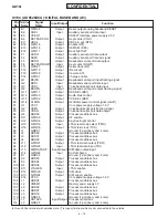
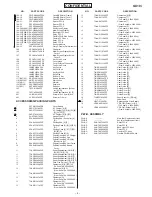
IC104 (AD6526XCA): DIGITAL BASEBAND (2/3)
Pin Terminal
Signal
Input/Output
Function
No.
Name
Name
57
E1
GPO24
Output
Reset output analog baseband RESET
58
E2
ASDI
Input
Auxiliary serial port data input
59
E3
VPEG1
–
AD6521 interface power supply 2.8 V
60
E4
KEYPADCOL1
Output
Key matrix (COL1)
61
E11
USC4
Output
USC pin out (RTS)
62
E12
GPO18
Output
Enable (RF)
63
E13
GPO16
Output
GSM SEL (BS0)
64
E14
GPO11
Output
Back light SW
65
F1
ASDO
Output
Auxiliary serial port data output
66
F2
ASFS
Output
Auxiliary serial port framing signal
67
F3
BSDO
Output
Baseband serial port data output
68
F4
KEYPADROW1
Input
Key matrix (ROW1)
69
F11
GPO21
Output
Serial clock (RF)
70*
F12
GPO10
Output
(Not used)
71
F13
GPO08
Output
Camera A18
72
F14
GPO07
Output
Charge enable
73
G1
BSIFS
Output
Baseband serial port input framing signal
74
G2
BSDI
Input
Baseband serial port data input
75
G3
VSDI
Input
Voiceband serial port data input
76
G4
BSOFS
Output
Baseband serial port output framing signal
77
G11
GPO17
Output
DCS SEL (BS1)
78
G12
GPO03
Output
Audio bias control
79
G13
GPO02
Output
PCS SEL (BS2)
80
G14
CLKON
Output
Oscillator power control signal (on/off)
81
H1
VCC1
–
Core power supply voltage 1.8 V
82
H2
VSFS
Output
Voiceband serial port framing signal
83
H3
VSDO
Output
Voiceband serial port data output
84
H4
ADD00
Output
Processor address bus
85
H11
GPO09
Output
RF enable
86
H12
GPO04
Output
Key back light control
87
H13
GPIO19
Input
JTAG test mode select (TMS)
88
H14
GPIO18
Output
JTAG test clock (TCK)
89
J1
GND01
–
Ground (7 periphery and 4 core)
90
J2
ADD02
Output
Processor address bus
91
J3
ADD01
Output
Processor address bus
92
J4
ADD03
Output
Processor address bus
93
J11
GPIO21
Output
JTAG test data output (TDO)
94
J12
GPIO20
Input
JTAG test data input (TDI)
95
J13
SIMDATAOP
Input/Output SIM data output/input
96
J14
GPIO22
Input
End of charge
97
K1
GND02
–
Ground (7 periphery and 4 core)
98
K2
ADD05
Output
Processor address bus
99
K3
ADD04
Output
Processor address bus
100
K4
ADD06
Output
Processor address bus
101
K11
JTAGEN
Input
JTAG enable
102
K12
SIMCLK
Output
SIM clock
103
K13
GPIO24
Output
SIM supply enable
104
K14
VCC3
–
Core power supply voltage 1.8 V
105
L1
ADD08
Output
Processor address bus
106
L2
VMEM1
–
Memory power supply 3 V
107
L3
ADD09
Output
Processor address bus
108
L4
ADD07
Output
Processor address bus
109
L5
ADD10
Output
Processor address bus
110
L6
GND04
–
Ground (7 periphery and 4 core)
111
L7
DATA05
Input/Output Processor data bus
112
L8
GND05
–
Ground (7 periphery and 4 core)
In this unit, the terminal with asterisk mark (*) is (open) terminal which is not connected to the outside.
Содержание GX10i
Страница 36: ...2 32 GX10i CONFIDENTIAL Point Figure 66 Contact points Push Figure 67 Turning power on ...
Страница 84: ...GX10i CONFIDENTIAL MEMO 4 5 ...
Страница 120: ...5 36 GX10i CONFIDENTIAL MEMO ...


