28
FU-28H-S
9. HOW TO REMOVE THE MOTOR
(1) Remove the Motor harness Cover in the direction
shown by the arrows, and then remove the Motor
harness.
* Hold down the areas marked with
@
with one hand
while lifting up and removing the Motor harness
Cover with the other hand.
Motor harness
Motor harness
Motor harness
Motor harness Cover
over
Motor harness
Motor harness Cover
(2) Remove the 4 Motor Angle screws (4 x 14 binding
head screws), and then lift up and remove the Motor
Angle.
Motor
Motor Angle
ngle
symbol: 4 x 14 mm screws
symbol: 4 x 14 mm screws
Motor Angle
symbol: 4 x 14 mm screws
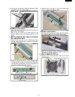
(3) Remove the Motor and the Front and Back Rubber
Cushions. And disconnect the motor harness from
the power supply PWB.
Back Rubber Cushion
Back Rubber Cushion
Front Rubber Cushion
Front Rubber Cushion
Motor
Motor
Back Rubber Cushion
Front Rubber Cushion
Motor
ASSEMBLY PRECAUTIONS
* When installing the Motor, set the Motor so that the
circled flange holes line up with the positions on the
Back Panel shown by the arrows.
* Make sure the Motor Angle and Motor do not make
contact.
Install so that the gaps
Install so that the gaps
are about the same.
are about the same.
Arrow mark
Arrow mark
Install so that the gaps
are about the same.
Arrow mark
(4) Remove the 2 screws (3 x 12 mm binding head
screws) and then pull out the AC Cord Angle and
Power Cord.
AC
AC Cord Angle
Cord Angle
Power Cord
Power Cord
symbol: 3 x 12 mm screws
symbol: 3 x 12 mm screws
AC Cord Angle
Power Cord
symbol: 3 x 12 mm screws
ASSEMBLY PRECAUTIONS
* When wiring, make sure none of the wires get
pinched.
* Insert the circled motor harness cover areas first.
ASSEMBLY PROCEDURE
Assemble in the reverse order of disassembly.
Assemble paying attention to the assembly precau-
tions written in the disassembly procedure.
Содержание FU-28H-S
Страница 16: ...16 FU 28H S 3 PRINTED WIRING BOARD ...
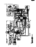
Страница 21: ...21 FU 28H S 6 CONTROL CIRCUITDIAGRAM ...

