25
FU-28H-S
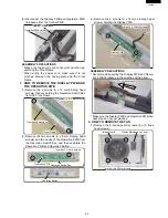
(2) Disconnect the Display PWB and Operation PWB
harnesses from the Control PWB.
Display PWB harness
Display PWB harness
Operation PWB harness
Operation PWB harness
Display PWB harness
Operation PWB harness
ASSEMBLY PRECAUTIONS
* Make sure the power cord is not pinched when as-
sembling the Front Frame.
* When wiring the power cord, make sure it is not
pinched between the casing plate and the Front
Frame.
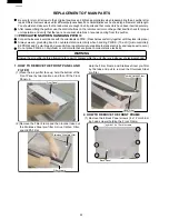
3. HOW TO REMOVE THE DISPLAY PWB AND
THE OPERATION PWB
(1) Remove the 2 screws (3 x 12 mm binding head
screws) that are holding the Operation Switch Box
from the Front Frame.
Front
Front Frame
rame
Operation
Operation Switch
witch Box
ox
symbol: 3 x 12 mm screws
symbol: 3 x 12 mm screws
Front Frame
Operation Switch Box
symbol: 3 x 12 mm screws
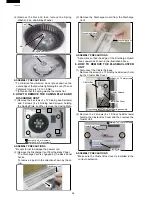
(2) Remove the two screws (3 x 8 mm binding head
screws) and two hooks of the Operation PWB from
the Operation Switch Box, and then separate the
Operation PWB and Operation Button.
Operation PWB
Operation PWB Operation
Operation Switch
witch Box
ox
symbol: 3 x 8 mm screws
symbol: 3 x 8 mm screws
Operation PWB Operation Switch Box
symbol: 3 x 8 mm screws
Operation
Operation Button
utton
Operation Button
(3) Remove the 2 screws (3 x 12 mm binding head
screws) holding the Display PWB.
Display PWB
Display PWB
symbol:
symbol: 3 x 12 mm screws
x 12 mm screws
Display PWB
symbol: 3 x 12 mm screws
ASSEMBLY PRECAUTIONS
* Assemble while pulling the Display PWB and Opera-
tion PWB harnesses in the direction of the arrow.
Pull the harness
Pull the harness
Pull the harness
* Make sure the Display PWB and Operation PWB har-
ness wires do not get pinched.
4. HOW TO REMOVE THE FAN
(1) Remove the 4 intake guard screws (4 x 10 truss
head screws).
symbol: 4 x 10 mm screws
symbol: 4 x 10 mm screws
Intake Guard
Cluster Maintenance Cover
symbol: 4 x 10 mm screws
Содержание FU-28H-S
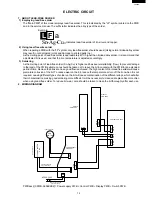
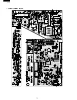
Страница 16: ...16 FU 28H S 3 PRINTED WIRING BOARD ...
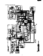
Страница 21: ...21 FU 28H S 6 CONTROL CIRCUITDIAGRAM ...

