


2
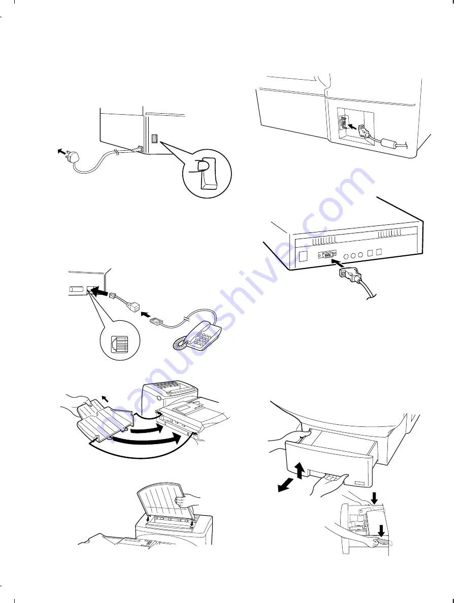
Plug the power lead into a 230V, 50Hz, earthed (3-prong) AC
outlet.
Press the power switch to turn on the power.
•
Caution: The mains outlet (socket-outlet) shall be installed
near the equipment and shall be easily accessible.
•
Important: Whenever you unplug the power lead, disconnect
the fax machine from the telephone network first.
3
If desired, you can connect a telephone to the fax machine. Insert
the end of the line for the telephone into the provided adaptor, and
then insert the adapter plug into the "TEL. SET" socket on the fax
machine.
•
The safety status of this socket is TNV, and is provided for the
connection of approved telephone equipment only. To ensure
continued safety compliance, do not connect any other equip-
ment to this socket.
4
Attach the original document OUT tray by inserting the tabs into
the holes in the fax as shown.
5
Attach the received document tray by inserting the tabs into the
holes in the fax as shown.
6
Insert the male end of the PC interface cable into the port on the
right side of fax as shown. Tighten the attached screws with a
screwdriver.
7
Insert the female end of the PC interface cable into the serial
(RS232C) port on your computer.
Tighten the attached screws with a screwdriver.
4. Loading printing paper
The paper cassettes and the paper tray hold the paper on which
received documents are printed. If needed, a second cassette (FO-
45A4) is available as an option from your dealer.
The paper cassette can hold 500 sheets of A4-size paper. The paper
tray can hold 150 sheets of A4-size paper.
1
Grasp the hand hold on the cassette as shown, lift the cassette
slightly, and then pull it out until it stops. Press down on the levers
on each side of the cassette to release it, and then pull it com-
pletely out of the fax using both hands.
OFF 0
ON |
TEL.
SET
FO-4500H
1 – 7
Содержание FO-4500
Страница 16: ...M E M O FO 4500H 1 14 ...
Страница 129: ...Control PWB parts layout Top side 6 11 FO 4500H ...
Страница 130: ...Control PWB parts layout Bottom side 6 12 FO 4500H ...
Страница 133: ...TEL LIU PWB parts layout 6 15 FO 4500H ...
Страница 134: ...6 16 FO 4500H ...
Страница 136: ...Power supply PWB parts layout 6 18 FO 4500H ...
Страница 141: ...M E M O 6 23 FO 4500H ...
Страница 149: ...Scanner unit Fig 6 Optical adjustment tool Fig 7 Fig 8 FO 4500H 8 6 ...


