


4) Auto feeder mode
The auto feed function can be checked by inserting and discharging
the document. (The distance between pages can be displayed during
operation of the scanner.)
1
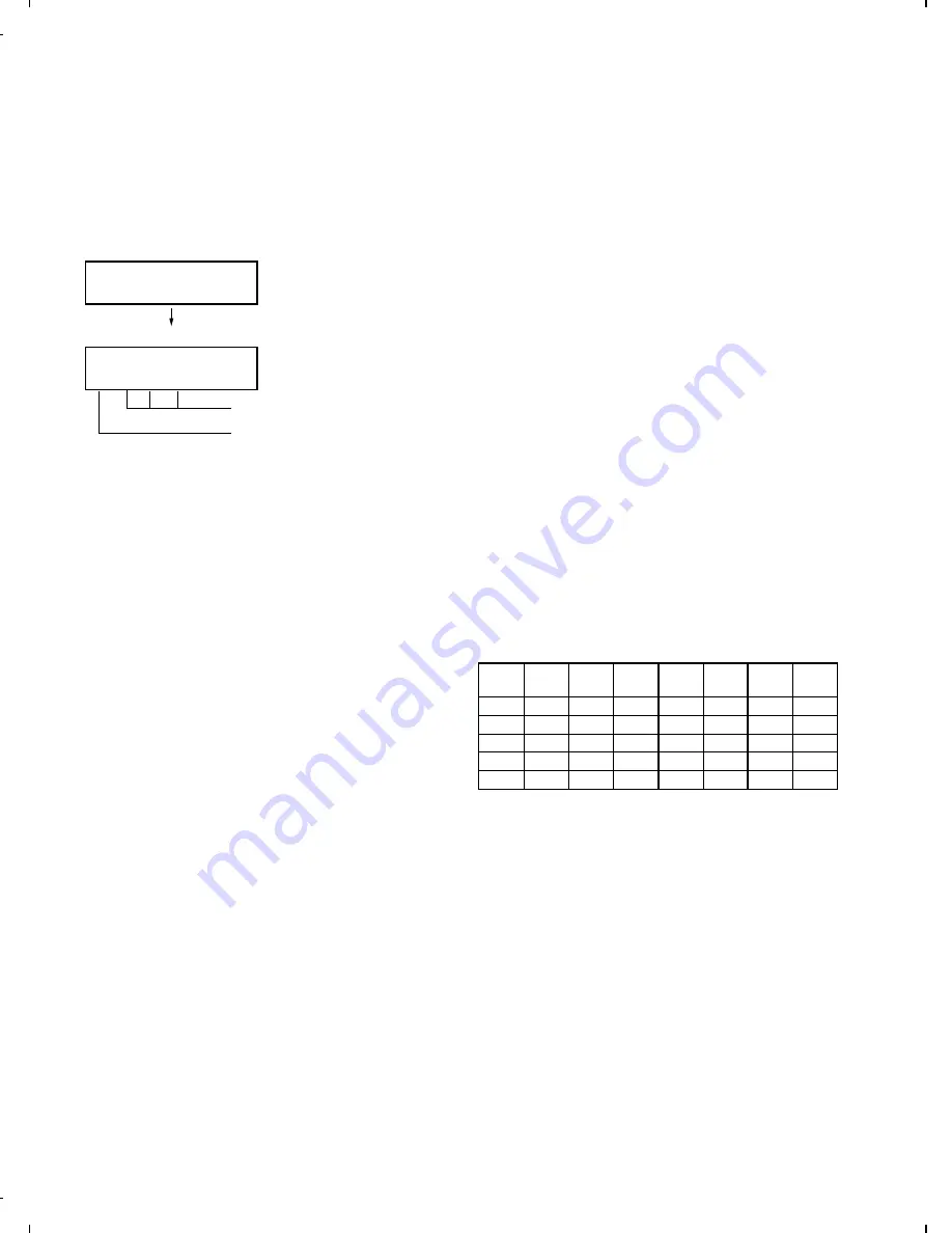
Check of auto feed function
After this mode is activated, set up the document, and press the
START key, and it will be automatically fed. (Before the START
key is pressed, the document sensor alone is activated.)
Moreover, the document size (A4/B4) and sensor information
(A4/B4/ORG) are displayed when the document sensor is turned.
2
Display of distance between pages during operation of the scan-
ner
•
Soon after this mode is c\activated, press the FUNCTION key
for 5 seconds or more, and the display mode of the distance
between pages will be activated. Then, set up the sending
paper and select the image quality, and then press the START
key, and operation will be started.
Be sure to press the FUNCTION key prior to the START key. If
the FUNCTION key is not pressed but the START key is
pressed, it will operate in the same manner as in the existing
auto feeder mode.
If the START key is pressed, the FUNCTION key will be invalid
hereafter. Therefore, the display mode of the distance between
pages and the existing mode can not be changed.
•
While the sending paper is read, the image quality key can be
input. STD/FINE/S-FINE modes are usable. However, the
same operation of FINE will be selected if the intermediate tone
is set.
•
The image quality, the length of the sending page read, the
page distance to the next sending paper and the total of the
sending papers read are shown on the display.
•
When the stop key is pressed or 100 sending papers are read,
the content shown on the display will be totally output as the list
after the remaining sending papers are discharged.
5) Aging mode
If any document is set up in the first state (when started), copying will
be executed. If it is not set up, "check pattern 1" of the print diagnosis
is output at the intervals of 1 time/60 minutes. (A total of 10 sheets
are output.)
6) Panel check mode
This is used to check whether each key is normally operated or not.
According to the key input, LCD is displayed. Moreover, during exe-
cution, the document reading lamp is turned on.
1
When [PANEL CHECK MODE] is displayed, press the [START]
key.
The test will be started. When the test is started, LED’s will se-
quentially come on. It is used to check all LED’s.
2
Press any other key except [STOP] key.
At this time, the name of each key will be displayed every push of
the key.
3
However, if any key is pressed with the page plate opened, it will
be equal to a press of key 32 with the page plate opened.
4
Finally press the [STOP] key.
If all keys can be input, the key input "ALL KEY OK!!" will be
displayed when the STOP key is ended.
The screen will be all displayed in black, and the test result will be
printed.
In this test, it is okayed if all the other keys except [STOP] key have
been pressed from start of the test to its end (the [STOP] key is
pressed). If any key is skipped, it will be regarded as "KEY ERROR!!",
and the name of the key not pressed will be printed on the list as the
result. This will complete printing.
7) Optical adjust mode
The document reading LED is turned on.
8) Product check
The diagnosis is used in the production process.
After shift to the mode, the following operations are sequentially exe-
cuted. At this time, the sensor of read-error can be checked by feed-
ing the B3 document. Set up one short document of B4 size.
1
Memory clear (Same as Diagnosis 11)
2
Panel test (Same as Diagnosis 06)
3
Dial test (Same as Diagnosis 22)
4
Document feed
5
Stamp press
6
ROM & RAM test, RS232C interface board check (Same as the
Diagnosis 03)
7
Flash memory test mode (Same as Diagnosis 12)
8
Registration of fixed data
Registration of rapid key No. and other data necessary for produc-
tion.
The registered data are shown in the following table. The chain
dial is not set for any destination.
Rapid
No.
FAX
No.
Rapid
No.
FAX
No.
Rapid
No.
FAX
No.
Rapid
No.
FAX
No.
01
20
06
25
11
1
21
01
02
21
07
26
12
2
22
02
03
22
08
27
13
3
23
03
04
23
09
28
14
4
24
04
05
24
10
29
15
5
25
05
9
Transmission check (Same as Diagnosis 10)
The soft switches necessary for production are set.
F
Test result print (two sheets)
• AUTO FEEDER CHECK LIST
• FLASH MEMORY CHECK LIST
Memory clear printing
Panel test result printing
ROM&RAM test result printing
Check result printing of RS232C interface board
G
Print area printing (one sheet)
04 : AUTO FEEDER MODE
04 : AUTO FEEDER MODE
B4 (A4 B4 ORG)
After setup of the document
Only the sensor which is
activated (fallen down) is displayed.)
The paper sheet size (A4/B4) is
displayed.
(
)
FO-4500H
2 – 4
Содержание FO-4500
Страница 16: ...M E M O FO 4500H 1 14 ...
Страница 129: ...Control PWB parts layout Top side 6 11 FO 4500H ...
Страница 130: ...Control PWB parts layout Bottom side 6 12 FO 4500H ...
Страница 133: ...TEL LIU PWB parts layout 6 15 FO 4500H ...
Страница 134: ...6 16 FO 4500H ...
Страница 136: ...Power supply PWB parts layout 6 18 FO 4500H ...
Страница 141: ...M E M O 6 23 FO 4500H ...
Страница 149: ...Scanner unit Fig 6 Optical adjustment tool Fig 7 Fig 8 FO 4500H 8 6 ...


