background image

AR-5618S ADJUSTMENT 6-9

'11/Jul/22

1

b. SPF original off-center adjustment (SIM50-12)

Note: Before performing this adjustment, be sure to check that the paper 

off center is properly adjusted. 

1) Make a test chart for the center position adjustment and set it on the 

SPF. 

<Adjustment specification>

Draw a line on a paper in the scanning direction. 
2) Make a normal copy from the bypass tray, and compare the copy 

and the original test chart.


If necessary, perform the following adjustment procedures. 

3) Execute SIM 50-12. 

4) After warm-up, shading is performed and the current set value of the 

off center adjustment at each paper feed port is displayed on the 
display section in 2 digits. 

5) Enter the set value and press the [START] key. 


The set value is stored and a copy is made. 

<Adjustment specification>

C.Image density adjustment

(1)Copy mode (SIM 46-2)

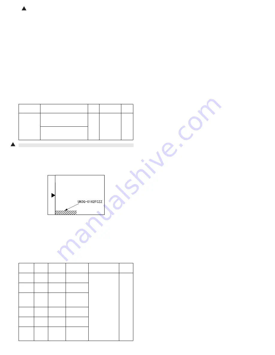
1) Set a test chart (UKOG-0162FCZZ) on the OC table as shown below.

2) Put several sheets of A3 or 11" x 17" white paper on the test chart. 

3) Execute SIM 46-2.
4) After warm-up, shading is performed and the current set value of the 

density level is displayed on the display section in 2 digits. 


For mode selection, use the AUTO/TEXT/PHOTO key. 

5) Change the set value with the Numeric keys to adjust the copy 

image density.

6) Make a copy and check that the specification below is satisfied.

<Adjustment specification>

Mode

Specification

SIM

Set value

Set

range

Original off 
center 
mode
(SPF mode)

Single:
Center ±3.0mm


(TEXT indicator)

SIM

50-12

Add 1:


0.1mm shift 
to R side
Reduce 1: 
0.1mm shift 
to L side

1 ~ 99

Duplex:
Center ±3.5mm


(PHOTO indicator)

Density 

mode

LED

Exposure 

level

Sharp Gray 

Chart output

Set value

Set 

range

Auto

Auto

-

"2" is slightly 
copied.

The greater the 
set value is the 
greater the 
density is The 
smaller the set 
value is the 
smaller the 
density is.

1 ~ 99

Text

Text

3

"3" is slightly 
copied.

Photo
(Error 
diffusion)

Photo

3

"2" is slightly 
copied.

Toner 
save

Auto/
Photo

-

"2" is slightly 
copied

Toner 
save

Text/
Photo

3

"3" is slightly 
copied

Photo
(Dither)

Auto/
Text/
Photo

3

"2" is slightly 
copied

1

Содержание AR-5618N

Страница 1: ...618S 5620S AR 5618N AR 5618D AR 5620 5623 AR 5620N 5623N AR 5620D 5623D 1 1 1 1 1 GENERAL 1 1 2 CONFIGURATION 2 1 3 SPECIFICATIONS 3 1 4 CONSUMABLE PARTS 4 1 5 EXTERNAL VIEWS AND INTERNAL STRUCTURES 5 1 6 ADJUSTMENTS 6 1 7 SIMULATIONS 7 1 8 TROUBLE CODE LIST 8 1 9 MAINTENANCE 9 1 10 DISASSEMBLY AND ASSEMBLY 10 1 11 OPERATIONAL DESCRIPTIONS 11 1 12 FLASH ROM VERSION UP PROCEDURE 12 1 13 ELECTRICAL ...

Страница 2: ...Disconnect the AC cord before servicing the unit LASER WAVE LENGTH 795 15mm Pulse times 0 481ms 6mm Out put power 5mW ...

Страница 3: ...n battery Must be disposed of properly Remove the battery from the product and contact federal or state environmental agencies for information on recycling and disposal options For USA CANADA CAUTION FOR BATTERY DISPOSAL ...

Страница 4: ... LIST 1 Trouble code list 8 1 2 Details of trouble codes 8 1 9 MAINTENANCE 1 Maintenance table 9 1 2 Maintenance display system 9 2 3 Note for replacement of consumable parts 9 2 10 DISASSEMBLY AND ASSEMBLY 1 High voltage section Duplex transport section 10 1 2 Optical section 10 2 3 Fusing section 10 4 4 Paper exit section 10 7 5 MCU NIC 10 9 6 Optical frame unit 10 9 7 LSU 10 10 8 Tray paper fee...

Страница 5: ...tments or performance of procedures other than those specified herein may result in hazardous laser radiation exposure The socket outlet shall be installed near the machine and shall be easily accessible C Note for installation place Improper installation may damage the machine Please note the following during initial installation and whenever the machine is moved Caution If the machine is moved f...

Страница 6: ...620N 5623N AR 5620D 5623D AR 5618N AR 5618D AR VR7 AR 5620 5623 AR 5618 AR SP10 1 1 1 MX NB12 S N model Option installation disable 1 MX USX1 Sharpdesk 1 license kit MX USX5 Sharpdesk 5 license kit MX US10 Sharpdesk 10 license kit MX US50 Sharpdesk 50 license kit MX USA0 Sharpdesk 100 license kit 11 Jul 22 1 ...

Страница 7: ...le pass feeder RSPF X X O AR SP10 Single pass feeder SPF X O X AR D36 250 sheet paper feed unit X O O AR D37 2x250 sheet paper feed unit X O O AR VR7 DOCUMENT COVER STD STD O MX NB12 NETWORK EXPANSION KIT X O O N model X MX USX1 SHARPDESK 1 LICENSE KIT X O O MX USX5 SHARPDESK 5 LICENSE KIT X O O MX US10 SHARPDESK 10 LICENSE KIT X O O MX US50 SHARPDESK 50 LICENSE KIT X O O MX USA0 SHARPDESK 100 LIC...

Страница 8: ...618 5620 5623 RSPF AR RP10 AR 5618N 5620N 5623N AR 5618D 5620D 5623D Network expansion kit MX NB12 AR 5618 5620 5623 AR 5618D 5620D 5623D Paper size AR 5623 AR 5623N AR 5623D AR 5620 AR 5620S AR 5620N AR 5620D AR 5618 AR 5618S AR 5618N AR 5618D A4 8 5 x 11 23ppm 20ppm 18ppm A4R 8 5 x 11 R 15 16ppm 14 15ppm 14 15ppm A5 5 5 x8 5 23ppm 20ppm 18ppm B5 16K 23ppm 20ppm 18ppm B5R 16KR 18 16ppm 16 15ppm 1...

Страница 9: ...r less Multi paper feed enable Heavy paper 129 200g m2 33 6 53 2lbs N A N A Yes A4 or less Only single paper feed Heavy paper 201 256g m2 53 3 68lbs N A N A N A Envelope 75 90g m2 20 24lbs N A N A Yes Postcard N A N A Yes OHP film N A N A Yes Label sheet N A N A Yes Tab paper 20 N A N A N A Max number of multi copy 999 sheets Warm up time 25 seconds or less Pre heat Available Jam recovery Within 2...

Страница 10: ... F service parts Duplex X O Toner save O Set according to the destination Account control O Copy 20 Dept 1 1 1 1 Photoconductor type OPC Organic Photo Conductor Photoconductor drum dia 30mm Copy lamp WhiteCCFL Developing system Dry 2 component magnetic brush development Charging system Saw teeth charging Transfer system DC corotron Separation system DC corotron Fusing system Heat roller Cleaning s...

Страница 11: ...P Vista 7 USB2 0 High Speed Windows2000 XP Vista 7 LPD IPP Raw Port Port9100 TCP IP Print by TCP IP port only for N model WSD WS Print Support WSD print only for N model BMLinks Print function Bar code Font N A Network Tandem Print N A Encrypted PDF PDF TIFF JPEG XPS Direct print N A Specify files by Web page to print Web Submit Print N A ROPM Yes Multi access support N A Paper direction setting f...

Страница 12: ...Scale 0 48msec line 400dpi Output data Mono 2 Levels Gray scale 8bit Full color Each color RGB 8bit Scan color Black white binary Gray scale Color Interface AR 5618 5620 5623 AR 5618D 5620D 5623D USB2 0 High speed mode full speed mode AR 5618N 5620N 5623N 10 100 base Internal full speed connection Scanner utility Button Manager Drop out color Yes Red Green Blue White Scanner button Provided 5 Supp...

Страница 13: ...document 2 Developer MX 235GV Developer x1 50K 3 Drum KIT AR 205DM Drum Drum fixing plate x1 x1 50K No Name Product name Content Life Remarke 1 Toner cartridge Black MX 235GT Toner cartridge Vinyl bag x1 x1 Default is Toner save mode Life is 19K Life setting by A4 6 document 2 Developer MX 235GV Developer x1 50K 3 Drum KIT AR 205DM Drum Drum fixing plate x1 x1 50K No Name Product name Content Life...

Страница 14: ...e production month No Name Product name Content Life Remark 1 Toner cartridge Black MX 235AT Toner cartridge Vinyl bag x1 x1 Default is Toner save mode Life is 19K Life setting by A4 6 document 2 Toner cartridge Black MX 236AT Toner cartridge Vinyl bag x1 x1 Default is Toner save mode Life is 10K Life setting by A4 6 document 3 Developer MX 235AV Developer x1 50K 4 Drum KIT AR 205DR Drum Drum fixi...

Страница 15: ...nt side Ver No Production place Serial number Year Month Day 1 2 3 4 5 6 7 8 9 10 1 Number For this model this digit is 2 2 Alphabet Indicates the model conformity code G for this model 3 Number Indicates the end digit of the production year 4 Number or X Y Z Indicates the production month X stands for October Y November and Z December 5 6 Number Indicates the day of the production date 7 Number I...

Страница 16: ...n 15 Charger cleaner 16 USB 2 0 connector Except for AR 5618N 5620N 5623N 17 10Base T 100Base TX LAN connector Except for AR 5618S 5620S 18 Document feeder tray when the SPF RSPF is installed 19 Original guides when the SPF RSPF is installed 20 Feeding roller cover when the SPF RSPF is installed 21 Right side cover when the SPF RSPF is installed 22 Exit area when the SPF RSPF is installed 23 Toner...

Страница 17: ...6 Alarm indicators 17 Display 18 Numeric keys 19 CLEAR key 20 INTERRUPT key indicator 21 Light and Dark keys indicators 22 PAPER SELECT key 23 AUTO PAPER SELECT indicator Except for AR 5618S 5620S 24 TRAY SETTING key 25 AUTO IMAGE key indicator 26 SPF RSPF indicator When the SPF RSPF is installed AR 5618N 5620N 5623N AR 5618 5620 5623 and AR 5618D 5620D 5623D 27 PRESET RATIO selector keys indicato...

Страница 18: ...ss tray paper transport clutch MPTC Drives the bypass tray paper transport roller 8 Bypass tray paper feed solenoid MPFS Bypass tray paper feed solenoid 9 2nd tray transport clutch FSCL1 Drives the 2nd tray transport roller AR 5620 5623 5620N 5623N 5620D 5623D only 10 2nd tray paper feed clutch PSCL2 Drives the 2nd tray paper feed roller AR 5620 5623 5620N 5623N 5620D 5623D only 11 Exhaust fan mot...

Страница 19: ...density in the developing unit 8 2nd tray detection switch CSD2 2nd tray detection 9 Bypass tray sensor MPED Bypass tray transport detection 10 2nd tray door open close sensor DRS2 2nd tray door open close detection AR 5620 5623 5620N 5623N 5620D 5623D only 11 2nd tray door paper pass sensor PPD2 2nd tray paper entry detection AR 5620 5623 5620N 5623N 5620D 5623D only 12 2nd tray paper empty senso...

Страница 20: ... Main control PWB Main control PWB 4 2nd tray PWB 2nd tray control 5 High voltage PWB High voltage control 6 Power PWB AC power input DC power control 7 Operation main PWB Operation panel input Display operation panel section control 8 USB I F PWB Connect a USB device Except for AR 5618N 5620N 5623N 9 Nic PWB Network interface PWB Except for AR 5618S 5620S 1 9 7 6 5 3 4 2 8 1 1 ...

Страница 21: ... box 11 Drum unit Forms images 12 Transfer charger unit Transfer images on the drum onto paper 13 DUP follower roller Transports paper for duplex 14 Duplex transport roller Transports paper for duplex 15 Resist roller Takes synchronization between the paper lead edge and the image lead edge 16 Bypass tray Bypass tray 17 Bypass tray paper pick up roller Picks up paper in bypass tray 18 No 2 3 mirro...

Страница 22: ...of the doctor plate of the developing unit to insure that it is 18mm If the distance is not within the specified range loosen the fixing screw A of the main pole adjustment plate and move the adjustment plate in the arrow direction to adjust Section Adjustment item Adjustment procedure SIM No A Process section 1 Developing doctor gap adjustment Developing doctor gap adjustment 2 MG roller main pol...

Страница 23: ...tment must be performed 1 Set a scale on the OC table as shown below 2 Make a copy 3 Check the copy output If necessary perform the following adjustment procedures 4 Execute SIM 50 1 5 Set the OC lead edge position set value PHOTO indicator ON to 1 The OC image scanning start position is shifted inside the document edge 6 Set the 1st tray lead edge void adjustment value TEXT indicator ON to 1 The ...

Страница 24: ...int surface lead edge position adjustment in advance and be sure to perform the 2nd print surface lead edge position adjustment and then the lead edge void adjustment in this sequence Adjustment specification Set to S D mode for before execution b SPF image lead edge position adjustment SIM50 6 1 Set a scale on the OC table as shown below Note Since the printed copy is used as a test chart put the...

Страница 25: ...justment SIM50 10 TEXT 1st tray indicator Adjustment specification e Side edge void area adjustment SIM26 43 Note Before performing this adjustment be sure to check that the paper off center adjustment SIM 50 10 is completed 1 Set a test chart UKOG 0089CSZZ on the document table 2 Select a paper feed port and make two copies Compare the 2nd copy and the test chart If necessary perform the followin...

Страница 26: ... contact with the positioning plate perform the adjustment of 4 4 Loosen the set screw of the scanner drive pulley which is not in contact with No 2 3 mirror base unit positioning plate 5 Without moving the scanner drive pulley shaft manually turn the scanner drive pulley until the positioning plate is brought into contact with No 2 3 mirror base unit then fix the scanner drive pulley 6 Put No 2 3...

Страница 27: ...n adjustment When there is no skew copy in the mirror base scanning direction and there is no horizontal error right angle to the scanning direction the adjustment can be made by adjusting the No 2 3 mirror base unit rail height Before performing this adjustment be sure to perform the horizontal image distortion adjustment in the laser scanner section This adjustment must be performed in the follo...

Страница 28: ...e or original glass Be careful to avoid this 5 Main scanning direction FR direction magnification ratio adjustment SIM 48 1 Note Before performing this adjustment be sure the CCD unit is within specification 1 Put a scale on the original table as shown below 2 Execute SIM 48 1 3 After warm up shading is performed and the current set value of the main scanning direction magnification ratio is displ...

Страница 29: ...ub scanning direction magnification ratio correction value is displayed in two digits on the display section 6 Enter the set value and press the START key The set value is stored and a copy is made 7 Change the mode from the duplex original mode to the simplex original mode TEXT indicator lights up and the current back surface sub scanning direction magnification ratio is displayed in two digits o...

Страница 30: ... several sheets of A3 or 11 x 17 white paper on the test chart 3 Execute SIM 46 2 4 After warm up shading is performed and the current set value of the density level is displayed on the display section in 2 digits For mode selection use the AUTO TEXT PHOTO key 5 Change the set value with the Numeric keys to adjust the copy image density 6 Make a copy and check that the specification below is satis...

Страница 31: ... and cooling fan operation check 03 Copy lamp lighting check 06 01 Paper feed solenoid clutch operation check 02 Resist roller solenoid clutch operation check 07 01 Warm up display and aging with jam 06 Intermittent aging 08 Shifting with warm up display 08 01 Developing bias output 02 Main charger output Grid HIGH 03 Main charger output Grid LOW 06 Transfer charger output 09 01 Duplex motor forwa...

Страница 32: ...cycle setting 12 Standby mode fusing fan rotation setting 13 Fusing paper interval control allow inhibit setting 44 01 Toner density control Enable Disable ON OFF setting 16 Toner density control data check and toner density control correction amount display 34 Transfer current setting 46 02 Copy density adjustment 600dpi 10 Copy exposure level adjustment individual setting Text 600dpi 11 Copy exp...

Страница 33: ... SPF and fix it with tape If paper is not fixed the operations cannot be guaranteed 02 SPF sensor status display Only when the SPF RSPF is installed In order to receive the sensor change notification the load must be decreased The sensor status ON OFF in the SPF can be checked with the following lamps When a sensor detects paper it turns on The open close detection sensor turns on when the machine...

Страница 34: ...ED lighting check mode all ON state When two or more keys are pressed simultaneously they are ignored 02 Fusing lamp and cooling fan operation check When the START key is pressed the fusing lamp turns ON for 500ms and OFF for 500ms The operation is repeated 5 times During this process the cooling fan motor rotates After completion of the process the machine goes into the sub code input standby mod...

Страница 35: ...ode with the AUTO TEXT PHOTO key and press the START key The transfer charger output is delivered for 30 sec in the selected mode After 30 sec of transfer charger output the machine goes into the sub code entry standby mode 09 01 Duplex motor forward rotation check Duplex model only The duplex motor is driven in forward direction in the paper exit direction for 30 sec During the process the displa...

Страница 36: ...erminated 04 Jam total counter display The jam total counter value is displayed 05 Total counter display The total counter value is displayed 06 Developing counter display The developing counter data is acquired and displayed on the 7 seg display When the Interrupt key is pressed the machine goes into the sub code input standby mode When the CA key is pressed the simulation is terminated 07 Mini m...

Страница 37: ...s out of the simulation mode 51 Drum rotation time display The drum rotation time is displayed Three digits are displayed alternatively When Interrupt key is pressed the display goes to the sub code input standby state When CA key is pressed the machine goes out of the simulation mode 24 01 Jam total counter clear When the START key is pressed the jam total count value is reset to zero and zero is...

Страница 38: ...the main motor rotates for 3 minutes to determine the toner sensor reference value and clear the developer rotation time as well as to clear the developer counter When the operation is completed normally the ATC sensor reference value is displayed on the entered value display section If an error occurs one of the following indicators is lighted This simulation must be executed only immediately aft...

Страница 39: ...nation setting When this simulation is executed the current set destination code number is displayed Enter the desired code number of the destination and press the START key to set the destination If this setting is changed SIM46 19 setting is also changed accordingly The paper size is also changed AB series is changed to A4 and Inch series to Letter The AUTO exposure limit setup is set to the def...

Страница 40: ...d 42 Transfer ON OFF timing control setting When this simulation is executed the current setting value of transfer ON timing is displayed Enter a set value and press the START key to set the entered value and the machine will go into the sub code input standby mode When the AUTO TEXT PHOTO key is pressed the ON timing setting and the OFF timing setting are alternatively selected At that time the s...

Страница 41: ...cuted the current code number is displayed on the 7 seg display 1 ON Correction is performed 0 OFF Correction is not performed Enter the code number and press START key and the setting is settled and written into the EEPROM and the machine goes into the sub code input standby mode Switching can be made with AUTO TEXT PHOTO key and the set value of the selected mode is displayed on the copy quantit...

Страница 42: ...ode Contents Details of operation LED Sensor name Developer replacement required indicator Misfeed indicator Copier Toner cartridge replacement required indicator Bypass tray indicator 1st tray indicator 2nd tray indicator 3rd tray indicator 4th tray indicator Misfeed indicator 1st tray Misfeed indicator 2nd tray Paper required indicator Paper exit sensor Duplex sensor Paper entry sensor Bypass tr...

Страница 43: ...s settled and saved into the EEPROM and the machine goes into the sub code input standby mode 13 Fusing paper interval control allow inhibit setting Used to set the paper feed timing of 21st and later page to A3 or WLT when multi copying or printing paper of narrow width A3 or WLT depends on the destination When this simulation is executed the currently set code number is displayed Enter a desired...

Страница 44: ...ed and the toner density control correction value is displayed on the 7 seg display The display mode can be switched by pressing AUTO TEXT PHOTO key When Interrupt key is pressed the machine goes into the sub code input standby mode When CA key is pressed the machine goes out of the simulation mode 34 Transfer current setting Used to set the transfer current for the front surface and that for the ...

Страница 45: ...overall brightness is increased The inclination value changes the gamma gradation When the set value is increased the gamma is increased to increase the contrast Clearer black and white images When the set value is decreased the gamma is decreased to decrease the contrast Increased gradation Press the key to switch between the shift amount and the inclination value The 7 seg display shows the mode...

Страница 46: ... set for the following three exposure modes Enter a code number and press the START key and the entered number is written into the EEPROM and the machine goes into the sub code entry standby mode When the AUTO TEXT PHOTO key is pressed the number is written into the EEPROM and the set item is changed Gamma table setting When this simulation is executed the current set code number of gamma table is...

Страница 47: ... toner save The set range is 0 255 The default is 196 Change the setting and press the START key and it will be written into the EEPROM and the machine will go into the sub code input standby mode When the AUTO TEXT PHOTO key is pressed the machine goes back to the gamma table setting mode Remark When SIM26 06 Destination setting and SIM46 19 Auto exposure mode are changed this set content of this...

Страница 48: ...to show the error position 02 Flash ROM program writing mode NNB The program is written into the NNB by using the USB memory Preliminary arrangement 1 Save the NNB download file to the root directory of the USB memory 2 Connect the USB memory to the USB port of the NNB Operating procedure When this simulation is executed d is displayed in the value section and the machine enters the NNB download m...

Страница 49: ...id amount B TEXT ON and the scan start position C PHOTO ON to 1 and make a 100 copy 2 Measure the image loss R mm of the scale Set as C 10 x R mm Example Set to 40 When the value of C is increased by 10 the image loss is decreased by 1mm Default 50 3 Measure the distance between the paper lead edge and the image print start position Set as A 10 x H mm Example Set to 50 When the value of A is incre...

Страница 50: ... with bypass tray use A3 paper When a document is scanned in the OC mode in the back surface center off set adjustment and printing is made in the S D mode the first document is scanned and then the second document is scanned automatically 12 Document off center adjustment Used to make the document scan off center adjustment Adjustment range 1 99 Default 50 When the adjustment value is increased b...

Страница 51: ...cument is scanned in the OC mode When printing is made in the S D mode the first document is scanned and then the second document is automatically scanned 19 Duplex copy rear edge void adjustment Duplex model only Used to adjust the rear edge void amount in duplex copy Operating procedure When this simulation is executed the current set value is displayed in two digits Adjustment range 1 99 Center...

Страница 52: ...document scan position select setting Setting is changed depending on whether the SPF unit and the SPF document glass holding section are glass dirt prevention parts or not For the combination of this machine and the AR SP10 RP10 the set value is set to 1 If the set value is changed to 0 black streaks may be produced on a copy paper due to dirt on the SPF glass When this simulation is executed the...

Страница 53: ...splayed on the 7 seg display and is not written into the EEPROM The pixel position 34 written into the EEPROM is considered as the SPF white correction start pixel of the machine When shi simulation is executed with the SPF unit closed an error will occur 64 01 Self print The optical system status is ignored and a self print is made Also when a print command is sent from the host printing is perfo...

Страница 54: ...face model is wrong Check and remedy 1 Use SIM26 39 to check to confirm that the memory capacity is 64MB If it is not 64MB replace the MCU PWB 2 If SIM26 04 is set to 1 change the setting to 0 If it is 0 replace the MCU PWB 02 Content LSU trouble Detail The BD signal from the LSU cannot be detected in a certain cycle Always OFF or always ON Cause LSU connector or LSU harness defect or disconnectio...

Страница 55: ... the MCU and the CRUM chip The CRUM identification error occurs Cause CRUM chip abnormality Developing unit disconnection MCU PWB abnormality Check and remedy Replace the toner cartridge Check installation of the developing unit Use SIM16 to cancel Replace the MCU PWB Main code Sub code Details of trouble F5 02 Content Copy lamp lighting abnormality Detail The copy lamp does not turn on Cause Copy...

Страница 56: ...k for disconnection of the heater lamp and the thermostat Check the interlock switch Check the power PWB and the lamp control circuit on the MCU PWB Cancel the trouble with SIM 14 Main code Sub code Details of trouble H5 01 Content 5 continuous POUT not reached error Detail When 5 continuous not reached jams to the paper exit sensor POUT occur The jam counter is backed up and it is used in a job a...

Страница 57: ... polygon motor the motor lock signal is detected for 20sec or more During rotation of the polygon motor the motor lock signal is detected for 1sec Cause Polygon motor unit abnormality Improper connection or disconnection of the polygon motor and the harness MCU PWB abnormality Check and remedy Use SIM 61 3 to check the polygon motor operations Check connection of the polygon motor harness connecto...

Страница 58: ...X X X X X Toner density sensor X X X X X X X Check the sensor head surface DV side seal F R X X X X X X X Optical section Reflector O O O O O O O Mirrors O O O O O O Pulley X X X X X X CCD Lens O O O O O O Table glass O O O O O O O White Plate O O O O O O O Drive wire X X X X X X Rail X X X X X X OC O O O O O O O LSU Dust proof glass O O O O O O O Paper feed section Manual feed take up roller O O ...

Страница 59: ...wing levels Remaining quantity display levels 100 75 50 25 10 LO c Press the Light keys Light and Dark keys to cancel Remaining quantity NEAR EMPTY About 10 EMPTY LED ON Flash Machine Operation allowed Stop Developer Life 50K LED ON at 50K of the developer count Machine Selection is available between Not Stop and Stop by Service Simulation SIM 26 37 Setup If Stop is selected the LED will flash and...

Страница 60: ...The charger wire must be free from twists or bending Be sure to put the charger wire in the V groove C Duplex transport section No Item 1 High voltage section Duplex transport section 2 Optical section 3 Fusing section 4 Paper exit section 5 MCU 6 Optical frame unit 7 LSU 8 Tray paper feed section Paper transport section 9 Bypass tray section 10 Power section 11 Developing section 12 Process secti...

Страница 61: ...e sure to put No 2 3 mirror unit to the positioning plate A Assembly Put the notched surface of wire holder 3 downward tighten temporarily and install Adjustment Main scanning direction distortion balance adjustment C Inverter PWB for copy lamp D Copy lamp No Content A Table glass B Copy lamp unit C Inverter PWB for copy lamp D Copy lamp E Lens unit F Wire 1 1 2 4 3 3 4 4 1 A A 2 3 3 1 3 2 1 1 2 1...

Страница 62: ... is loosened the position and the angle of the CCD unit base may be changed to cause a problem which cannot be adjusted in the market In that case the whole scanner unit must be replaced 5 Slide the CCD unit in the arrow direction CCD sub scanning direction to change the installing position When the copy image is longer than the original scale shift the CCD unit in the direction B When the copy im...

Страница 63: ...ng section A Fusing unit removal B Thermostat 1 2 3 4 4 No Contents A Fusing unit B Thermostat C Thermistor D Heater lamp E Upper heat roller F Separation pawl G Lower heat roller H Separation pawl 3 2 3 point special screw 2 M4 x 8 2 M3 x 8 1 1 1 2 3 2 ...

Страница 64: ...n the fusing frame Assembly Put the fusing harness A on the heater lamp B as shown in the figure and fix them together R Place the fusing harness inside the rib C E Upper heat roller Disassembly There are three pawls on the fusing cover Remove the screws and slide the fusing cover to the right to remove The heater lamp is fixed on the fusing cover with a screw Slide the fusing cover to the front a...

Страница 65: ...paper guide 3 temporarily fix the paper guide fixing plate with the screw so that the paper guide fixing plate 2 is in contact with the fusing lower frame bottom A Lower the fusing front paper guide to the bottom of the adjustment width and tighten the screw firmly Note I apply grease JFE552 to a fusing lower frame lib 1 1 2 Grease JFE552 Floil GU2 1 2 3 2 3 2 3 2 3 1 1 3 2 2 A 4 Grease JFE552 Gre...

Страница 66: ... exit unit No Content A Ozone filter B Cooling fan C Paper exit unit D Paper exit sensor duplex sensor E Transport roller F Paper exit roller 1 1 1 2 1 1 1 S model N model 1 1 2 Standard model D model 1 1 2 2 3 N model 2 1 S model 2 3 Standard D model 2 3 1 1 2 4 2 2 2 2 1 3 1 2 3 3 5 5 1 1 3 2 1 4 4 6 11 Jul 22 1 ...

Страница 67: ...r E Transport roller F Paper exit roller Assembly Insert the spring pin so that the waveform A of the spring pin faces in the longitudinal direction of the paper exit drive gear long hole B R Be sure to insert two ribs C into the groove D A B 1 1 2 1 1 2 3 4 5 3 1 1 2 A B D C C 1 1 2 2 2 3 11 Jul 22 1 ...

Страница 68: ...Note When replacing the MCU PWB be sure to replace the EEPROM of the MCU PWB to be replaced B NIC disassembly 6 Optical frame unit A Optical frame unit Installation Install the optical unit in the sequence shown above No Content A MCU disassembly B NIC disassembly 3 2 2 2 2 1 2 2 2 3 2 No Content A Optical frame unit 2 1 1 1 1 1 1 1 ...

Страница 69: ...wer outlet Adjustment Image lead edge position adjustment Image left edge position adjustment Paper off center adjustment 8 Tray paper feed section Paper transport section A Middle frame unit Assembly Do not miss the door lock pawl No Content A LSU unit 2 4 2 2 2 2 1 3 1 3 3 1 4 2 2 3 1 2 No Content A Middle frame unit B Drive unit C PS clutch Resist roller D Paper feed clutch Paper feed roller E ...

Страница 70: ...tch rotation stopper is securely engaged in the frame C PS clutch Resist roller D Paper feed clutch Paper feed roller E Connection gear unit 2 1 3 6 4 5 7 1 1 2 3 7 4 5 6 1 2 4 3 1 1 3 2 4 5 6 1 Apply rice grain sized grease HANARL to the front surface of the specified gear Grease G 484 for the drive section ...

Страница 71: ... installing direction of the bypass tray transport roller 6 B Bypass tray paper feed C Bypass tray solenoid When installing the solenoid shift it in the arrow direction and install No Content A Bypass tray transport roller Bypass tray paper feed roller B Bypass tray paper feed C Bypass tray solenoid D Bypass tray transport clutch E Pressure plate unit F Bypass tray paper feed clutch A A A 3 4 5 2 ...

Страница 72: ...E Pressure plate unit F Bypass tray paper feed clutch Note Push the lever at the right edge of the multi frame cover to the right upper side and remove it 1 2 3 4 5 Apply grease FG 40H to the gray area UKOG 0004QSZZ 2 1 3 2 1 3 1 1 2 A A A 2 2 3 1 3 1 2 4 Apply grease FG 40H to the gray area UKOG 0004QSZZ ...

Страница 73: ...0 14 10 Power section A Power unit B High voltage P W B C Power P W B D Power switch No Content A Power unit B High voltage P W B C Power P W B D Power switch 1 1 1 1 2 1 1 1 1 3 2 2 2 2 2 2 2 2 2 2 2 2 2 1 2 1 2 2 3 2 2 1 1 11 Jul 22 1 ...

Страница 74: ...le position adjustment Note Attach it to fit with the attachment reference when replacing the DV blade No Contents A Developing box B Developing doctor C MG roller 2 3 3 3 4 1 1 2 5 4 3 3 0 0 5 0 0 5 Attaching reference DV blade Mark off line Mark off line reference The DV blade surface must be free from foreign materials Do not touch the DV blade tip It must be free from deflection ...

Страница 75: ... clean and remove the dirt 2 Apply KYNAR to prevent blade flip Check method Check to confirm that the OPC drum is free from fingerprints or oily dirt and that the cleaning blade is completely cleaned by the following method Make a print of a half tone image on all the surface of A4 11 x 8 5 paper and check the printed paper for any abnormality in the image 2 Prior exposure prevention Note Avoid se...

Страница 76: ... Contents A Operation P W B B Tray interface P W B C 2nd tray paper entry sensor Paper empty sensor D 2nd tray transport clutch E 2nd tray transport roller F 2nd tray paper feed clutch G Main motor H Paper entry sensor I Paper empty sensor 3 4 3 1 2 5 5 5 6 7 5 2 3 1 1 1 1 1 1 2 1 1 2 2 2 1 1 3 ...

Страница 77: ...nsor Paper empty sensor Disassembly When the second paper feed unit is detached the screw is removed and the main body is lifted D 2nd tray transport clutch E 2nd tray transport roller F 2nd tray paper feed clutch G Main motor 2 3 5 1 4 1 2 1 3 2 1 1 2 3 4 1 2 1 2 3 ...

Страница 78: ...AR 5618S DISASSEMBLY AND ASSEMBLY 10 19 H Paper entry sensor I Paper empty sensor 1 1 2 3 1 2 3 ...

Страница 79: ...nd a paper feed clutch does ON and a paper feed roller turns A transportation clutch does ON and the paper is sent to the transportation department By a separation plate to prevent against double feed of paper Main motor Transportation clutch Paper feed clutch Tray detection switch Paper pass sensor Transport roller Paper feed roller Separation plate Door open close sensor Paper empty sensor ...

Страница 80: ...ct c Maintenance Downtool 2 Download procedure 1 Main body side Executable by performing the Service Simulation No 49 01 Flash Rom program writing mode A word d appears on the operation panel to denote the download mode status 2 Connect the PC and the main body with the download cable USB cable 3 PC side Boot the maintenance program Select the model icon Sample display 4 PC side Confirm that the S...

Страница 81: ... maintenance program at the time of the USB being re connected Repeat the previous procedures from the above 5 Forbidden actions while downloading Important Failure in the download concerned may not allow you to conduct the subsequent download procedures Added care should be taken to avoid having the situation below arise while downloading Switching off the main body Disconnecting the download cab...

Страница 82: ...on When the driver is included in the C Sirius folder 6 Check that the path to the folder which includes the maintenance tool driver Mainte inf is shown and press the NEXT button 7 Check that the following display is shown Press the Continue Anyway button 8 When installation is completed the following display is shown Press the Finish button The installation procedure on Windows XP is completed wi...

Страница 83: ...er which includes the maintenance tool driver Mainte inf and press the OPEN button Check that the path to the folder which includes the maintenance tool driver Mainte inf is properly displayed and press the OK button When the maintenance tool driver is included in the folder of D Sirius 8 Press the NEXT button and installation is started 9 When installation is completed the following display is sh...

Страница 84: ...N and select Set the OP Address 5 Press Yes 6 Check to confirm that Ethernet Address of the installed NIC PWB is displayed and select Ethernet Address and press Next 7 Enter the IP address and press Next If an error screen is not displayed the IP address setting is completed 8 Set the IP address of the download PC to the fixed IP address the same segment set to the machine in the procedure 4 9 Boo...

Страница 85: ...6MH䌺 Supplied from ClockGen ASIC Reset SSCG Driver 16bit Shift Reg 2pcs 7seg LED LED 3 3V HC151 KEY 3 3V START KEY POWER SUPPLY POFF HL PR FW 5VEN 24V HVU TC䋬GRID䋬MC䋬BIAS PMCLK 16 20cpm 2078 74Hz 23cpm 2881 89Hz PSW KEYIN SELIN1 2 3 OP CLK OP LATCH OP DATA OP BEO LED PSL ONL MHPS VIDEO S H APCSTT SYNC SPMT0 1 2 3 Driver SPFCLH SPFPSOL Sensor Driver Selector L1 2 W0 1 2 3 SPFCOVER PAPER SPFOPEN SPF...

Страница 86: ...2 0 2 40 55 55 66 2 40 55 55 66 59 40 55 4106 18 4 59 6 5 18 4 59 6 610 4 1614 0 1614 8 70 6 47 4 7 40 55 8 40 55 5 18 4 59 40 55 2 4 8 2 2 8 5 59 40 55 25 40 55 2 86 2 08 2 08 㧔4GF㧕 2 8 㧔 㧕 57 7 40 55 2 5 9JKVG 5ECPPGT 2 JCTPGUU 27 55 9JKVG 40 55 6 40 55 40 55 㨯 40 55 25 40 55 0 1614 40 55 2 8 9JKVG 2 4 6 4 0 6 0 29 75 OQFGN QPN 0 7 JCTPGUU 126 10 1 0 8 0 4 7 614 126 10 0 OQFGN QPN 12 2QYGT 2 8 9...

Страница 87: ...2 A2 0 0 0 2 4 A2 A2 A5 A5 A 2 A 2 5 2 5 2 0 2 4 A45 A45 8R QHH 8R QHH 0 0 2 0 2 0 A6 A6 0 0 85 2 85 2 4 4 2 0 0 8 8 8R QHH 8R QHH 0 0 8 8 8 8 0 2 0 0 8R QHH 8R QHH 0 0 2 26 2 26 0 0 4 2 0 6 8 0 0 2 5 2 0 5 66 5 66 0 10 0 0 8 4 2 0 2 0 2 4 47 8R QHH 8R QHH 47 0 25 25 0 0 0 0 4 2 2 4 4 2 4 0 2 5 2 2 8 5 2 4 8 0 176A 8 8 176A 251 251 176A 2 176A 7 29 57 70 6 352 57 7 40 55 0 2 2 4 26 5 0514 29 2 35 ...

Страница 88: ...0 2 08 6 6 8 5 0 2 08㧔4GF㧕 0 0 2 4 2 5 0 2 5 8 5 8 8 6 5 6 5 85 85 2 0 2 0 0 2 4 0 0 8 2 5 6 8 4 5 6 5 2 0 5 A 47 5 A 47 5 A 47 5 A 47 8 8 0 0 2 2 8 5 8 4 0 0 2 8 6 A1 6 A1 9 7 29 25 29 352 25 40 55 352 59 40 55 0 9 9 59 25 0 14 35 8 40 55 352 4 7 40 55 4 2 4 14 2 47 4 2 4 14 2 0 6 4 56 4 75 0 70 6 352 40 55 0 6 40 55 8 1PN 8 70 6 6 5 87 29 2 9 9 4 35 40 55 35 㨯 40 55 35 6 40 55 352 40 55 5QEMGV Q...

Страница 89: ...5 0 㪪 㪄 㪭 㪍 㪉 㪄 㪧 㪛 㪬 㪧 㪥 㪠 㪧 㪌 㪉 㪬 㪙 㪘 㪪 㪄 㪛 2 5 2 4 8 2 2 8 5 1 5 2 2 5 1 5 2 8 8 5 2 4 8 2 2 8 5 8 8 8 5 0 0 5 0 5 2 5 2 8 8 5 8 0 5 0 5 5 0 2 5 2 2 4 2 7 7 2 2 7 7 2 0 5 0 5 4 2 2 4 2 2 5 2 5 5 2 8 0 5 4 8 0 451 52 451 8 8 27 2 8 5 0 2 5 8 51 2 4 2 4 0 2 5 8 0 0 2 5 4 2 5 0 5 0 52 176 52 176 8 8 2 5 2 㪪㪩㪘㪄㪉㪈㪫㪄㪊 㪋 㪄 㪫 㪈 㪉 㪄 㪘 㪩 㪪 㪋 㪄 㪫 㪈 㪉 㪄 㪘 㪩 㪪 52 452 10 52 1614 52 51 52 451 2 2 4 064 5 0514...

Страница 90: ...㪝㪈㪈㪄㪍㪛㪧㪄㪪㪧㪈㩿㪇㪅㪌㪀 㪛㪝㪈㪈㪄㪏㪛㪧㪄㪪㪧㪈㩿㪇㪅㪌㪀 0 0 5 4 8 0 5 2 8 0 8 8 0 27 55 2 8 4 8 2 8 4 8 25 25 5 4 8 0 5 2 8 0 0 8 8 5 5 2 8 4 8 0 5 0 5 0 8 8 0 25 0 0 0 5 0 8R QHH 5 0 8R QHH 0 0 0 5 0 5 8 8 25 8R QHH 8R QHH 2 0 2 0 0 5 25 0 25 5 2 0 2 0 5 25 5 0 5 0 8R QHH 8R QHH 5 0 2 0 2 0 0 0 25 5 25 5 25 5 8 8 8 8 8 0 0 8 8R QHH 0 5 0 5 0 5 0 8R QHH 0 2 0 0 5 0 0 2 0 25 5 25 8 2 0 2 0 5 0 25 5 25 5 25 0 5 0 8R QHH...

Страница 91: ...5 A 75 0A 156 A 75 A 0 0 0 0 ޓ 2 5 2 2 8 5 2 2 8 5 0 2 5 0 0 4 A 6 4 7 A 6 A 6 7 5 6 A 6 4 7 A 5 6 4 A 6 7 5 6 4 A 6 4 7 A 5 6 A 6 7 6 A 6 4 7 A 4 A 6 7 0 6 0 P 6 5 4 A 7 6 5 4 1 2 1 2 2 7 9 P 2 7 9 P 0 0 8 0 0 5 4 8 0 5 2 8 0 5 0 8 8 2 0 8 2 0 8 2 0 4 8 8 8 8 8 0 5 0 5 0 0 0 4 8 4 6 7 0 4 6 7 0 8 4 0 8 4 0 75 156 VJGT 0 6 75 8 0 29 352 75 40 55 00 29 9 25 29 12 25 29 352 0 7 40 55 75 29 7 29 7 29...

Страница 92: ...free solder is about 220 C which is about 40 C higher than that of conventional lead solder and its soldering capacity is inferior to conventional one it is apt to keep the soldering iron in contact with the PWB for longer time This may cause land separation or may exceed the heat resistive temperature of components Use enough care to separate the soldering iron from the PWB when completion of sol...

Страница 93: ... Windows Server 2008 and Internet Explorer are registered trademarks or trademarks of Microsoft Corporation in the U S A and other countries PostScript is a registered trademark of Adobe Systems Incorporated Macintosh Mac OS AppleTalk EtherTalk Laser Writer and Safari are registered trademarks or trademarks of Apple Inc IBM PC AT and Power PC are trademarks of International Business Machines Corpo...

Отзывы: