
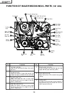


9
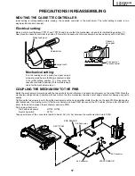
13VT-R100/R150
13VT-CR10
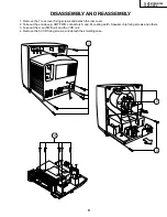
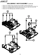
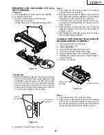
1. Remove the 7 rear cover fixing screws and detach the rear cover.
2. Take out the anode cap, CRT PWB, connectors K and M, coating earth, Speaker chip fixing screws and others.
3. Take out the main PWB unit and the VCR unit.
4. Remove the 5 VCR fixing screws, and detach the shielding case.
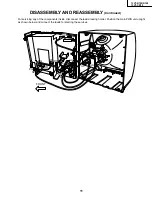
DISASSEMBLY AND REASSEMBLY
1
3
2
K
M
4
Содержание 13VT-CR10
Страница 55: ...57 13VT R100 R150 13VT CR10 56 12 11 10 9 8 7 6 5 4 3 2 1 A B C D E F G H BLOCK DIAGRAM OF TV SECTION ...
Страница 62: ...69 13VT R100 R150 13VT CR10 68 12 11 10 9 8 7 6 5 4 3 2 1 A B C D E F G H OVERALL SCHEMATIC DIAGRAM ...
Страница 64: ...71 13VT R100 R150 13VT CR10 6 5 4 3 2 1 A B C D E F G H SCHEMATIC DIAGRAM CRT Unit ...
Страница 72: ...85 13VT R100 R150 13VT CR10 6 5 4 3 2 1 A B C D E F G H PWB C POWER Unit Component Side ...
Страница 73: ...86 13VT R100 R150 13VT CR10 6 5 4 3 2 1 A B C D E F G H PWB A MAIN Unit Component Side ...
Страница 74: ...87 13VT R100 R150 13VT CR10 6 5 4 3 2 1 A B C D E F G H PWB A MAIN Unit Chip Parts Side ...