


42
13VT-R100/R150
13VT-CR10
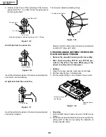
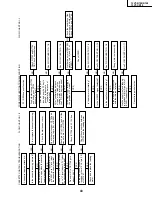
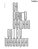
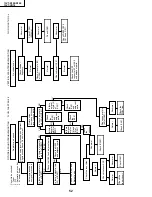
TROUBLESHOOTING OF VCR SECTION
NO
NO
NO
NO
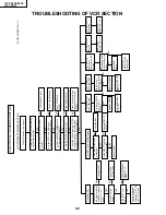
The VCR is dead. (No Power)
YES
YES
Unplug the AC power cord. Replug
it a few minutes later.
Are the AT 5V and AT 12V lines
normal?
YES
Are the AT 5V and GND lines
properly connected with IC2001?
Is there oscillation (14MHz) at pin
(37) and (38) of IC2001?
Check the sensor inputs to IC2001
from mechanism. (CAM switches,
start/end sensors & reel sensors)
YES
YES
YES
YES
YES
YES
YES
YES
YES
YES
Are the PC 5V lines normal?
Check power circuit.
Check all sensors and
their connections with
IC2001.
Check power circuit.
Check poor soldering.
NO
NO
Change IC2001.
Check the tape.
Replace IC2001
Check IC2001.
NO
NO
NO
NO
Check X7701 and
IC2001.
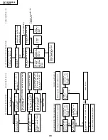
No power(5V).
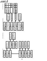
Only REC key is not functioning.
Is the PC 5V line
normal?
Does power control
(H) signal at pin (4)
of IC2001 change
from "L" to "H"
level?
Check peripheral
circuit for poor
soldering of PC 9V
and PC 5V lines.
Check IC765.
(PC 9V GEN)
Replace REC TIP
SWITCH.
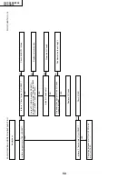
Is the tape in the write
protection?
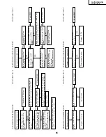
After loading for 3
secs, tape stop.
Are there H.SW.P
at pin (23) of
IC2001?
See FLOWCHART
NO. 1-10.
YES
YES
Replace IC2001
NO
NO
Are there reel
pulse at pin (2) and
(3) of IC2001?
After loading finish,
is the loading stop
rotate?
Check the
pressure of the
pinch roller.
See FLOWCHART
NO. 1-11.
Check CAM
switch
After loading for 5
secs, tape stop.
When loading,
pinch roller
doesn't touch the
capstan.
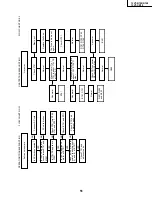
FF/REW key not
function.
Only Eject key is
functioning.
See FLOW
CHART NO. 1-3.
See FLOW
CHART NO. 1-2.
Is the REC TIP switch
normally function?
NO
Check IC756 and
Q756.(PC 5V
GEN)
Is the PC 9V line
normal?
FLOW CHART NO.1-1
ELECTRICAL TROUBLESHOOTING
VCR POWER TROUBLESHOOTING
Содержание 13VT-CR10
Страница 55: ...57 13VT R100 R150 13VT CR10 56 12 11 10 9 8 7 6 5 4 3 2 1 A B C D E F G H BLOCK DIAGRAM OF TV SECTION ...
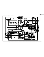
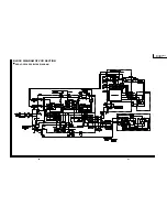
Страница 62: ...69 13VT R100 R150 13VT CR10 68 12 11 10 9 8 7 6 5 4 3 2 1 A B C D E F G H OVERALL SCHEMATIC DIAGRAM ...
Страница 64: ...71 13VT R100 R150 13VT CR10 6 5 4 3 2 1 A B C D E F G H SCHEMATIC DIAGRAM CRT Unit ...
Страница 72: ...85 13VT R100 R150 13VT CR10 6 5 4 3 2 1 A B C D E F G H PWB C POWER Unit Component Side ...
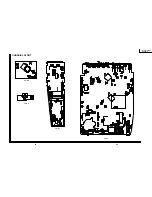
Страница 73: ...86 13VT R100 R150 13VT CR10 6 5 4 3 2 1 A B C D E F G H PWB A MAIN Unit Component Side ...
Страница 74: ...87 13VT R100 R150 13VT CR10 6 5 4 3 2 1 A B C D E F G H PWB A MAIN Unit Chip Parts Side ...


