


53
13VT-R100/R150
13VT-CR10
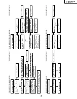
FLOW CHART NO.2-5
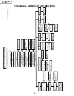
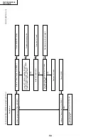
SOUND TROUBLESHOOTING
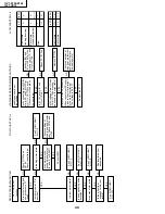
PLAYBACK SOUND TROUBLESHOOTING
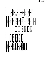
PLAYBACK PICTURE TROUBLESHOOTING
FLOW CHART NO.2-7
No sound
FLOW CHART NO.2-6
No playback picture
YES
YES
YES
YES
YES
YES
YES
YES
YES
YES
Is there a signal at pin
(55) of IC401?
Check the TV
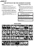
TROUBLESHOOTING :
"NO SOUND".
NO
NO
NO
No playback sound
Check IC401 and
adjacent parts.
Check the VCR
TROUBLESHOOT-
ING : "NO
SOUND".
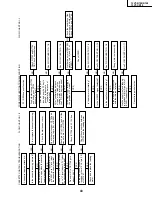
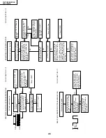
FLOW CHART NO.2-8
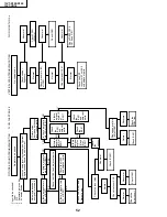
Does the infrared remote control
function?
Is 5V applied at pin (2) of the
remote control receiver?
Is fluorescent lighting enough away
from the set?
Is there short-circuit in the key input
or IC2001?
Check IC2001.
Check the 5V and GND lines.
Check key input terminals.
Replace the infrared remote control
as required.
Check pin (14) of IC2001 and /or
receiver.
Reposition the set not to be
exposed to strong light.
Is "L" pulse given out of pin (1) of
the receiver and received at pin (14)
of IC2001, when the infrared remote
control is activated?
No operation is possible from the
infrared remote control.
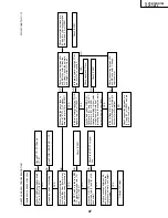
Does waveform appear
at pin (54) of IC401?
Check IC351 and
adjacent parts.
Check AT8V line and
C361.
Does approx. 8V appear
at pin (5) of IC351?
Check IC401 and
adjacent as same as "NO
PICTURE".
Does waveform appear
at pin (54) of IC401?
NO
NO
NO
NO
NO
NO
NO
Check the VCR
TROUBLESHOOT-
ING : "NO
PLAYBACK".
Is there a signal at pin
(39) of IC401?
INFRARED R/C TROUBLESHOOTING
Содержание 13VT-CR10
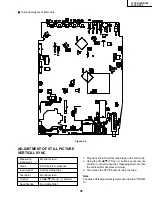
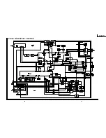
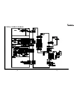
Страница 55: ...57 13VT R100 R150 13VT CR10 56 12 11 10 9 8 7 6 5 4 3 2 1 A B C D E F G H BLOCK DIAGRAM OF TV SECTION ...
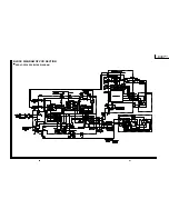
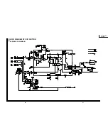
Страница 62: ...69 13VT R100 R150 13VT CR10 68 12 11 10 9 8 7 6 5 4 3 2 1 A B C D E F G H OVERALL SCHEMATIC DIAGRAM ...
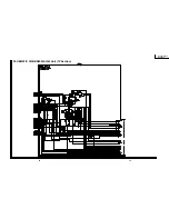
Страница 64: ...71 13VT R100 R150 13VT CR10 6 5 4 3 2 1 A B C D E F G H SCHEMATIC DIAGRAM CRT Unit ...
Страница 72: ...85 13VT R100 R150 13VT CR10 6 5 4 3 2 1 A B C D E F G H PWB C POWER Unit Component Side ...
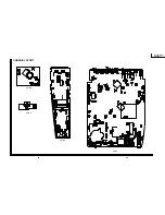
Страница 73: ...86 13VT R100 R150 13VT CR10 6 5 4 3 2 1 A B C D E F G H PWB A MAIN Unit Component Side ...
Страница 74: ...87 13VT R100 R150 13VT CR10 6 5 4 3 2 1 A B C D E F G H PWB A MAIN Unit Chip Parts Side ...


