


43
13VT-R100/R150
13VT-CR10
FLOW CHART NO.1-2
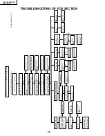
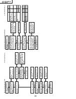
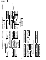
CASSETTE CONTROL TROUBLESHOOTING
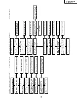
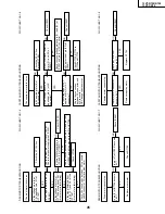
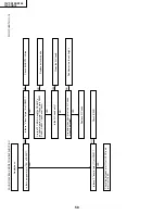
FF/REW DISFUNCTION TROUBLESHOOTING
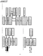
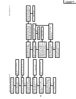
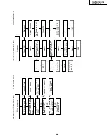
FLOW CHART NO.1-3
A cassette tape is not taken in.
YES
YES
YES
YES
YES
YES
YES
YES
YES
YES
YES
NO
NO
NO
NO
NO
YES
YES
YES
YES
NO
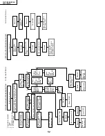
Are both start sensor, Q7703
and end sensor, Q7704
become "H" level?
Is the master cam rotating in
the position of FF mode?
Is the drum motor rotating?
After the cassette tape is
inserted and the FF key is
pushed, is it become
"confirmation balance of
tape" mode?
After "confirmation balance
of tape" mode finish,is the
loading motor rotated when
the FF / REW key is pushed?
FF / REW does not function.
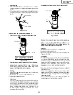
Is the cassette housing distored?
Fix or replace the cassette housing.
Check the start sensor cover.
Check the start sensor, Q7703 and
the way up to pin (79) of IC2001.
NO
Check Q7703 and Q7704.
OR Check cassette tape.
NO
See FLOW CHART NO. 1-8.
NO
NO
See FLOW CHART NO. 1-5.
See FLOW CHART NO. 1-6.
Is the H.SW.P. signal detected?
Cassette tape is defective.
See FLOW CHART NO. 1-10.
Is the capstan motor rotating?
See FLOW CHART NO. 1-8.
Is the wheel that connected
with the idle reel rotating?
Change idle reel assembly.
Are the supply reel and take up
reel pulses at pin (3) and (2) of
IC2001, respectively?
See FLOW CHART NO. 1-11.
NO
Check IC2001.
NO
NO
NO
NO
NO
Are there a normal CAM SW
signal at pin (6) and (7) of
IC2001?
Check the condition of the
master cam and relay gear.
Check D7704 and D7705.
Check pin (91) of IC2001 and all the
way up to pin (11) of IC7706.
Check IC7706 and AT 12V line.
Check the connection between
IC7706 and the loading motor.
Does pin (21) of IC7706 go to
about 13.4V?
Check and replace the loading
motor.
Does the start sensor cover
become open when the cassette
tape is inserted?
Does the start sensor pin (79)
of IC2001 go to "L" level when
the cassette tape is inserted?
Does pin (11) of IC7706 (LB1988)
go to "H" level (about 4.7V) when
the cassette tape is inserted?
At the time the cassette is
inserted, is there 12V at pin (13)
of IC7706?
Содержание 13VT-CR10
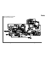
Страница 55: ...57 13VT R100 R150 13VT CR10 56 12 11 10 9 8 7 6 5 4 3 2 1 A B C D E F G H BLOCK DIAGRAM OF TV SECTION ...
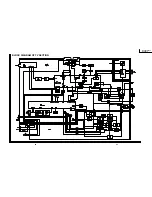
Страница 62: ...69 13VT R100 R150 13VT CR10 68 12 11 10 9 8 7 6 5 4 3 2 1 A B C D E F G H OVERALL SCHEMATIC DIAGRAM ...
Страница 64: ...71 13VT R100 R150 13VT CR10 6 5 4 3 2 1 A B C D E F G H SCHEMATIC DIAGRAM CRT Unit ...
Страница 72: ...85 13VT R100 R150 13VT CR10 6 5 4 3 2 1 A B C D E F G H PWB C POWER Unit Component Side ...
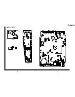
Страница 73: ...86 13VT R100 R150 13VT CR10 6 5 4 3 2 1 A B C D E F G H PWB A MAIN Unit Component Side ...
Страница 74: ...87 13VT R100 R150 13VT CR10 6 5 4 3 2 1 A B C D E F G H PWB A MAIN Unit Chip Parts Side ...