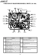
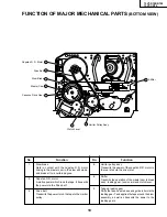


32
13VT-R100/R150
13VT-CR10
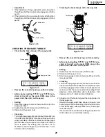
ADJUSTMENT OF TAPE DRIVE TRAIN
1. Tape run rough adjustment
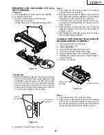
1
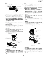
Remove the cassette housing control assembly.
2
After shortcircuiting TP7701 and TP7702 provided
at the main PWB, plug in the power cord, then turn
on the power.
3
Check and adjust the position of the tension pole.
(See page 28.)
4
Check and adjust the video search rewind back
tension. (See page 27.)
5
Connect the oscilloscope to the test point for PB
CHROMA envelope output (TP3301). Set the syn-
chronism of the oscilloscope to EXT. The PB
CHROMA signal is to be triggered by the head
switching pulse (TP3302).
6
Set the alignment tape (VRONBZGS) to play. (Put
a 500g weight on the cassette tape to prevent lift of
cassette tape.)
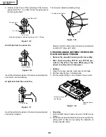
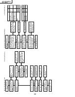
Figure 1-31.
7
Press the tracking button (+), (–) and change the
envelope waveform from max to min and from min
to max. At this time make sure that the envelope
waveform changes nearly parallel.
8
Unless the envelope waveform changes nearly
parallel, adjust the height of supply side and take-
up side guide roller so that the envelope waveform
changes nearly parallel. (For envelope adjustment
procedure refer to Figure 1-35.)
9
Turn the tilt screw to remove the tape crease at the
fixing guide flange.
Play back the tape and check for tape crease at the
fixing guide flange.
(1) If there is no tape crease
Turn the tilt screw clockwise so that tape crease
appears once at the flange, and then return the
tilt screw so that the crease disappears.
(2) If there is tape crease
Turn counterclockwise the tilt screw so that the
tape crease disappears.
(Reference) If the tilt screw is turned clockwise
crease appears at the lower flange.
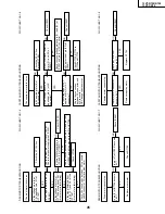
Guide roller
Weight of 500g
Cassette Tape
Notes:
1. Previously set the tracking control in the center posi-
tion, and adjust the envelope waveform to maximum
with X value adjustment nut. Thereby the tape run
rough adjustment is facilitated.
2. Especially the outlet side envelope waveform must
have higher flatness.
Figure 1-32.
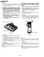
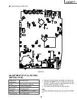
2. Adjustment of A/C head height and azimuth
1
Perform the initial setting of A/C head position by
the method stated in "Page 30 Replacement 3".
2
Connect the oscilloscope to the audio output
(TP6601).
3
Using the alignment tape in which 1 kHz linear
audio signal has been recorded, adjust the height
screw so as to get max audio output.
4
Using the alignment tape in which 7 kHz linear
audio signal has been recorded, adjust the azi-
muth screw so as to get max audio output.
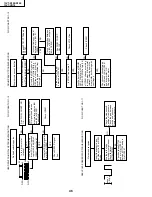
Figure 1-33.
For X value adjustment
Adjust the X value, turning the gear-
type screwdriver.
500g
Содержание 13VT-CR10
Страница 55: ...57 13VT R100 R150 13VT CR10 56 12 11 10 9 8 7 6 5 4 3 2 1 A B C D E F G H BLOCK DIAGRAM OF TV SECTION ...
Страница 62: ...69 13VT R100 R150 13VT CR10 68 12 11 10 9 8 7 6 5 4 3 2 1 A B C D E F G H OVERALL SCHEMATIC DIAGRAM ...
Страница 64: ...71 13VT R100 R150 13VT CR10 6 5 4 3 2 1 A B C D E F G H SCHEMATIC DIAGRAM CRT Unit ...
Страница 72: ...85 13VT R100 R150 13VT CR10 6 5 4 3 2 1 A B C D E F G H PWB C POWER Unit Component Side ...
Страница 73: ...86 13VT R100 R150 13VT CR10 6 5 4 3 2 1 A B C D E F G H PWB A MAIN Unit Component Side ...
Страница 74: ...87 13VT R100 R150 13VT CR10 6 5 4 3 2 1 A B C D E F G H PWB A MAIN Unit Chip Parts Side ...


