


41
13VT-R100/R150
13VT-CR10
Measuring
Monitor screen
instrument
Mode
EP still picture playback
Input signal
Self-recording tape
Test point
Monitor screen
Control
CH
'
/
"
(TR
±
/
—
) buttons
Specification
No Vertical jitter
1. Play back the EP Self-recorded tape in the still mode.
2. Using the CH
'
/
"
(TR
±
/
—
) buttons on the remote
control or on the front pannel, make adjustment so that
the vertical jitter becomes minimum.
3. Then press the STOP button to stop the tape.
Note:
The data of this adjustment is memorized to the E
2
P-ROM
IC.
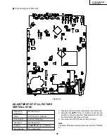
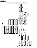
ADJUSTMENT OF STILL PICTURE
VERTICAL SYNC
Figure 2-2.
Ë
Test points layout of Main Unit.
Содержание 13VT-CR10
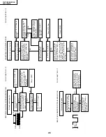
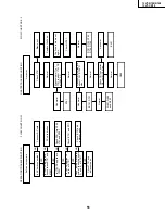
Страница 55: ...57 13VT R100 R150 13VT CR10 56 12 11 10 9 8 7 6 5 4 3 2 1 A B C D E F G H BLOCK DIAGRAM OF TV SECTION ...
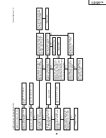
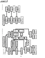
Страница 62: ...69 13VT R100 R150 13VT CR10 68 12 11 10 9 8 7 6 5 4 3 2 1 A B C D E F G H OVERALL SCHEMATIC DIAGRAM ...
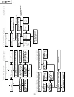
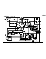
Страница 64: ...71 13VT R100 R150 13VT CR10 6 5 4 3 2 1 A B C D E F G H SCHEMATIC DIAGRAM CRT Unit ...
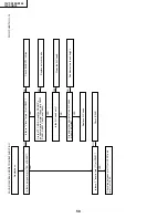
Страница 72: ...85 13VT R100 R150 13VT CR10 6 5 4 3 2 1 A B C D E F G H PWB C POWER Unit Component Side ...
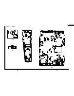
Страница 73: ...86 13VT R100 R150 13VT CR10 6 5 4 3 2 1 A B C D E F G H PWB A MAIN Unit Component Side ...
Страница 74: ...87 13VT R100 R150 13VT CR10 6 5 4 3 2 1 A B C D E F G H PWB A MAIN Unit Chip Parts Side ...


