


36
13VT-R100/R150
13VT-CR10
1
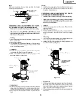
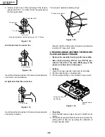
Insert Reverse Guide Lever Ass’y
Figure 1-41-1.
Phase Matching Point
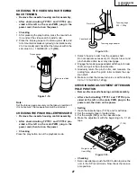
2
Pinch Roller Double
Action Lever Ass'y
Open lever
Insert reverse guide lever ass'y
Align here.
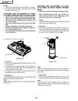
2
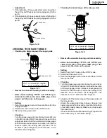
Insert pinch drive cam
Pinch drive lever ass'y
Fit the pinch drive cam so that the notch of pinch
drive cam aligns with the dent of pinch drive lever
assembly.
Fit the pinch drive cam so that the notch of
pinch drive lever assembly aligns with the
half-round notch of chassis.
Turn the reverse guide lever
assembly counterclockwise
to the stopper.
2
Insert Pinch Roller/Pinch Double Action Lever Ass’y.
Figure 1-41-2.
Figure 1-41-3.
3
Insert Open Lever.
Содержание 13VT-CR10
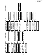
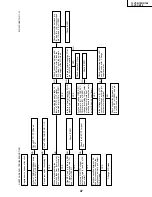
Страница 55: ...57 13VT R100 R150 13VT CR10 56 12 11 10 9 8 7 6 5 4 3 2 1 A B C D E F G H BLOCK DIAGRAM OF TV SECTION ...
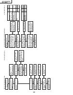
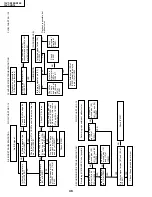
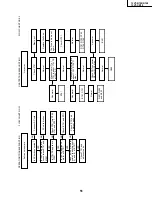
Страница 62: ...69 13VT R100 R150 13VT CR10 68 12 11 10 9 8 7 6 5 4 3 2 1 A B C D E F G H OVERALL SCHEMATIC DIAGRAM ...
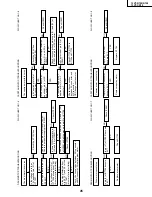
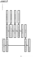
Страница 64: ...71 13VT R100 R150 13VT CR10 6 5 4 3 2 1 A B C D E F G H SCHEMATIC DIAGRAM CRT Unit ...
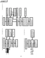
Страница 72: ...85 13VT R100 R150 13VT CR10 6 5 4 3 2 1 A B C D E F G H PWB C POWER Unit Component Side ...
Страница 73: ...86 13VT R100 R150 13VT CR10 6 5 4 3 2 1 A B C D E F G H PWB A MAIN Unit Component Side ...
Страница 74: ...87 13VT R100 R150 13VT CR10 6 5 4 3 2 1 A B C D E F G H PWB A MAIN Unit Chip Parts Side ...


