


90
Operating Instructions – MOVITRAC® B
5
Communication and unit profile
Startup
Special cases of
PO data process-
ing
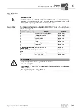
Setting the process output data description separately allows for a great variety of com-
binations. Not all of them are technically meaningful, however.
In addition to the process output data, the digital input terminals are generally also used.
In special cases, also the analog setpoint of the MOVITRAC
®
B frequency inverter is
used.
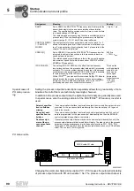
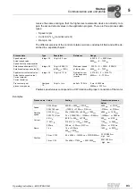
PO data enable
Changing the parameter
Setpoint description PO1 - PO3
causes the automatic disabling
of process output data with
PO data enable = No
. The process output data channel is
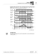
RAMP
Set to
RAMP
, the MOVITRAC
®
B frequency inverter interprets the
transmitted setpoint value as an acceleration or deceleration
ramp. The specified value corresponds to a time in ms and refers
to a speed change of 3000 rpm.
The rapid stop and emergency stop function is not affected by this
process ramp. When transmitting the process ramp via fieldbus
system, ramps t11, t12, t21 and t22 become ineffective.
1 digit = 1 ms
CONTROL WORD
1 / CONTROL
WORD 2
The assignment of process output data with control word 1 or 2
allows for activating nearly all the drive functions via fieldbus sys-
tem. For a description of control words 1 and 2, please refer to the
chapter "Control word definition".
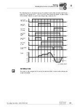
SPEED [%]
Set to
SPEED [%]
means the MOVITRAC
®
B frequency inverter
interprets the setpoint transmitted in this process data word as
speed setpoint in percent.
The relative speed setpoint always refers to the currently applica-
ble maximum speed limit, which means either P302/312 or MAX.
SPEED or PO speed limit.
4000
hex
= 100% n
max
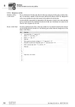
IPOS PO-DATA
The setting
IPOS PO-DATA
has the effect that the frequency
inverter does not use this process output data word for processing
setpoints. The inverter system ignores the content of the process
output data word programmed to
IPOS-PO-DATA
and is available
for sole processing in the IPOS
plus®
control program.
Within IPOS
plus®
, you can use the command
GetSys PO-Data
to
directly access the process output data of the communication
interfaces. For more detailed information, refer to the IPOS
plus®
positioning and sequence control system manual.
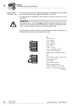
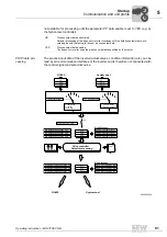
Three words
with individually
coded 16 bits
each can be
exchanged
between the
higher-level con-
troller and
IPOS
plus®
.
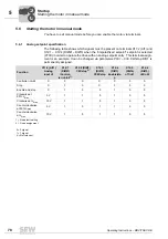
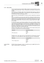
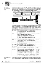
Assignment
Meaning
Scaling
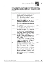
Setpoint specifica-
tion via fieldbus
missing
If a communication interface is entered as setpoint source and if no setpoint is pro-
grammed for the process output data description, then the setpoint = 0 is gener-
ated in the inverter.
No control word
specification via
fieldbus
If a communication interface is entered as control signal source and if no control
word is programmed for the process output data description, then the ENABLE
control command is specified in the inverter.
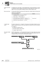
Double assign-
ment of the pro-
cess output data
channel
If several process output data words have the same setpoint description, only the
process output data word that is read first will apply. The order in which the process
output data words are processed in the frequency inverter is PO1 - PO2 - PO3.
This means if PO2 and PO2 have the same setpoint description, only PO2 will take
effect. The content of PO3 is ignored.
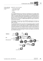
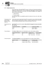
5946336651
PO 1
PO 2
Process output data
PO 3
P876: Enable PO data
00
I
Содержание Movitrac B
Страница 2: ...SEW EURODRIVE Driving the world...
Страница 259: ......


