


74
Operating Instructions – MOVITRAC® B
5
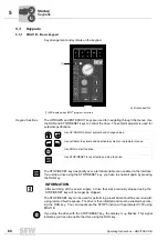
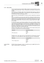
Short description of important startup steps
Startup
5.5
Short description of important startup steps
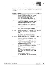
You can directly connect the MOVITRAC
®
B frequency inverter to a motor with the same
power rating. For example: A 1.5 kW (2.0 HP) motor can be connected directly to a
MC07B0015.
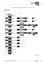
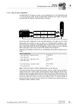
5.5.1
Procedure
5.5.2
Notes
Signal terminal functions and setpoint settings can be modified using the FBG11B key-
pad or a PC. A PC connection requires the FSC11B front module or one of the following
interface adapters: UWS21B / UWS11A / USB11A.
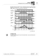
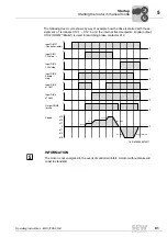
1. Connect the motor to MOVITRAC
®
B
(terminal X2).
2. You have the option of connecting a
braking resistor (terminal X2/X3).
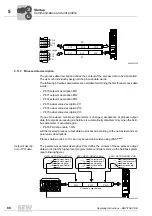
3. The following signal terminals must be
controlled with your control system:
• Enable DIØ3
• As required: CW/STOP DIØ1 or
CCW/STOP DIØ2
• Setpoint:
• Analog input (X10) and/or
• DIØ4 = n11 = 150 rpm or / and
• DIØ5 = n12 = 750 rpm or / and
• DIØ4 + DIØ5 = n13 = 1500 rpm
• For brakemotors:
DOØ2 = brake control via brake rec-
tifiers
4. You have the option of connecting the
following signal terminals:
• DIØØ = fault reset
• DOØ1 = /malfunction (designed as a
relay contact)
• DOØ3 = ready
5. Check the controller for the required
functionality.
6. Connect the frequency inverter to the
mains (X1).
53520267
Brake released*
}
n13 = n11 + n12
3-phase
REF1
24VIO
Enable/stop*
GND
PE
X2
X3
PE
3-phase
1-phase
Changeover
Reference potential analog signals
Fault reset
CW/stop
CCW/stop
Supply voltage
input/output
Reference potential binary signals
Reference potential
Ready
Reference potential
Relay contact/fault
NOC relay
NCC relay
Shield clamp
Factory setting
00
I
Содержание Movitrac B
Страница 2: ...SEW EURODRIVE Driving the world...
Страница 259: ......


