Site design
UltraWave Product Guide
Page 13
Relay contact ratings
The dry contact relays are Form C, rated for 30 V @ 1 A maximum, non-inductive load. In Remote
control mode, you can configure the relays as steady ON, flash mode (ON-OFF-ON-OFF, etc.), or
pulse mode (ON for a period, then OFF). For flash and pulse modes, the relay Active/Inactive
times are selectable. In Local control mode the relays remain active for the event’s duration or for
the selectable Hold Time, whichever is longer.
Cable ports
Each UltraWave unit includes two 21.5 mm (0.844 in.) cable ports. The post-mounting kit
(E4KT0300) includes two compression glands for cable sizes 4.3 mm to 11.4 mm (0.17 in. to
0.45 in.). If required, the enclosure can be fitted with 13 mm (1/2 in.) conduit, in place of the
compression glands.
Mounting posts/surfaces
The UltraWave units mount easily on posts with an outside diameter ranging between 4.8 cm and
11.4 cm (1.875 in. and 4.5 in.). The posts must be plumb, firmly set in the ground, and unable to
rotate or move. For areas where the ground freezes, the posts must be protected against potential
frost heaving. A 2.5 m (8 ft.) post is generally used with 91 cm (3 ft.) of the post buried in a
concrete footing.
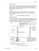
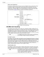
is an illustration of a post-mounted UltraWave unit.
Note
Conduit and conduit fittings are not included.
Note
Senstar recommends hiring a local fencing contractor to install
the UltraWave mounting posts.
Consult the local building code for information on installing
mounting posts.
Figure 8 Post installation and unit mounting
4.8 to 11.4 cm post
power and alarm
wiring in conduit
ground wire
ground rod
UltraWave unit
mounting height from
center of antenna to ground
ground level
buried conduit
to alarm panel
& power supply
rebar
through post
concrete footing
Consult the local construction codes for information about using
concrete footings in ares where ground freezing occurs.
*
vertical pitch
adjustment
bolts (X2)
For UltraWave pairs that are separated
*
by 50 m (164 ft.) or less, mount each
unit with a 5º pitch toward the ground.
alignment holes
(To obtain a 5º mounting angle, line up
the alignment holes on the mounting
are lined up
bracket and post collar).
Содержание UltraWave E4FG0101
Страница 1: ...Product Guide UltraWave Microwave Detection Sensor E4DA0402 001 Rev E August 27 2019 ...
Страница 30: ...Page 30 UltraWave Product Guide ...
Страница 44: ...Page 44 UltraWave Product Guide ...
Страница 46: ...Page 46 UltraWave Product Guide ...
Страница 52: ...Page 52 UltraWave Product Guide ...


