Site design
Page 6
UltraWave Product Guide
You can calculate the required minimum clearance between the beam centerline and an object by
using the following formula:
(transmitter/receiver separation) X 0.02 = (min. distance between beam centerline and object)
The formula can also be used to calculate the maximum separation between the transmitter and
receiver when you know the available clearance between the beam centerline and the nearest
object:
(transmitter/receiver separation) = (min. distance between beam centerline and object) / 0.02
Zone length
The optimum length of each zone depends on several factors:
•
the required level of security
•
physical constraints (terrain, trees, fences, buildings, etc.)
•
available space for the detection zone
For a
high-security
zone
, the maximum zone length is 90 m (295 ft.) and the maximum distance
between the transmitter and receiver is 100 m (328 ft.). The terrain must be level to grade ± 7.5 cm
(3 in.) and the surface must be free of vegetation and either paved, or covered with a 10 cm (4 in.)
layer of crushed stone (2 cm {0.75 in.} max.).
For a
medium-security
zone
, the maximum zone length is 140 m (459 ft.) and the maximum
distance between the transmitter and receiver is 150 m (492 ft.). The terrain must be level to grade
± 15 cm (6 in.) and the surface must be paved, or covered with crushed stone, or hard packed dirt
or clay, or closely mowed grass.
For a
low-security zone
, the maximum zone length is 200 m (656 ft.) and the maximum distance
between the transmitter and receiver is 200 m. The terrain must be level to grade ± 23 cm (9 in.)
and the surface must be paved, or covered with crushed stone, or hard packed dirt or clay, or
closely mowed grass.
Zone height
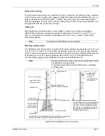
The height of the microwave field is approximately equal to the minimum required clearance
between the beam centerline and an object (see
) plus the unit mounting height
(e.g., for a microwave pair with a unit separation of 75 m the zone height is approximately
1.5 m + 0.47 m = 1.97 m or 6.46 ft.). For applications that require additional zone height it is
possible to stack two, or three UltraWave units on one mounting post.
provides
approximate zone heights based on Height Calculator tool recommendations.
triple stacked UltraWave configuration. Open the UCM Height Calculator tool and select Double
Stack, or Triple Stack configuration. Enter the unit separation and the Height Calculator tool will
provide the installation details.
transmitter/receiver separation
min. required clearance
(beam centerline to object)
midpoint zone width
30 m (98 ft.)
0.6 m (2 ft.)
1.2 m (4 ft.)
50 m (164 ft.)
1.0 m (3.3 ft.)
2.0 m (6.6 ft.)
75 m (246 ft.)
1.5 m (5 ft.)
3 m (10 ft.)
90 m (295 ft.)
1.8 m (6 ft.)
3.6 m (12 ft.)
100 m (328 ft.)
2.0 m (6.6 ft.)
4.0 m (13.2 ft.)
125 m (410 ft.)
2.5 m (8.2 ft.)
5.0 m (16.4 ft.)
150 m (492 ft.)
3.0 m (10 ft.)
6.0 m (19.7 ft.)
200 m (656 ft.)
4.0 m (13.2 ft.)
8.0 m (26.3 ft.)
Table 1 Unit separation/minimum clearance
Содержание UltraWave E4FG0101
Страница 1: ...Product Guide UltraWave Microwave Detection Sensor E4DA0402 001 Rev E August 27 2019 ...
Страница 30: ...Page 30 UltraWave Product Guide ...
Страница 44: ...Page 44 UltraWave Product Guide ...
Страница 46: ...Page 46 UltraWave Product Guide ...
Страница 52: ...Page 52 UltraWave Product Guide ...


