Setup
UltraWave Product Guide
Page 37
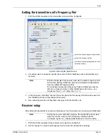
3. Select the Resistor 1 value, if applicable.
4. Select the Resistor 2 value, if applicable.
5. Set the Noise Tolerance, if required.
6. Set the Line Drop, if required.
7. Set the Filter Window.
8. Save and download the configuration changes to the receiver.
Output relays
Output relay setup (Local control mode)
In Local control mode, the two relays are setup via the Local Aux Control Activation check boxes to
report alarm and supervision conditions. The relays are then controlled by the UltraWave unit to
activate on the user-specified conditions. The relays remain active for an event’s duration or for
the selectable relay Active Time, whichever is longer.
1. Select a relay (the parameters listed below a relay apply only to that relay).
2. Specify the Hold/Active Time parameter.
3. Specify the conditions from the Local Aux Control Activation field under which this relay will
activate.
4. Repeat this procedure for the second relay.
5. Save and download the configuration changes to the UltraWave unit.
Output relay setup (Remote control mode)
In Remote control mode, the receiver’s relays are controlled by the security management system
to operate auxiliary equipment as output control points (e.g., to activate lights, doors, sirens, CCTV
equipment, etc.). The transmitter’s relays operate only in Local control mode. You configure the
relays response to commands from the host computer. You can configure the relays as steady ON,
or in flash mode (ON-OFF-ON-OFF etc.) or in pulse mode (ON for a period, then OFF). For flash
and pulse modes, the ON-OFF time duration is configurable.
1. Select a relay (the parameters listed below a relay apply only to that relay).
2. Select the type of relay Activation (steady ON, or flash mode, or pulse mode).
3. Select the Hold/Active Time parameter, if applicable.
4. Select the Inactive Time parameter, if applicable.
5. Repeat this procedure for the second relay.
6. Save and download the configuration changes to the receiver.
Note
Senstar recommends that the relay outputs be configured to report Tx
Comm Link Fail, Input Power Fail, and Fail Safe conditions, in
addition to Microwave Alarms.
Содержание UltraWave E4FG0101
Страница 1: ...Product Guide UltraWave Microwave Detection Sensor E4DA0402 001 Rev E August 27 2019 ...
Страница 30: ...Page 30 UltraWave Product Guide ...
Страница 44: ...Page 44 UltraWave Product Guide ...
Страница 46: ...Page 46 UltraWave Product Guide ...
Страница 52: ...Page 52 UltraWave Product Guide ...


