


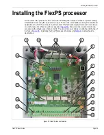


Installing the FlexPS processor
Page 58
FlexPS Product Guide
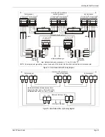
For Silver Network based processors using Remote control mode, a processor’s audio output is
placed on the audio bus in response to commands from the security management system. For
processors using Local control mode, closing a contact across the Aux inputs activates the audio
output (Aux 1 = A-side, Aux 2 = B-side, see
).
Input/output wiring connections
You make FlexPS processor wiring connections on removable terminal blocks. The screw
terminals accept wire sizes from 12 to 24 AWG, with a 6.4 mm (0.25 in.) strip length. Remove the
terminal blocks to make the wiring connections. Reinstall the blocks after the connections are
complete, and verified.
shows the MEX sensor cable to processor connection
procedure.
shows the input/output wiring connections to the FlexPS processor.
to
show the Silver Network wiring options.
Figure 65: Audio bus connection diagram
T10
FLEX CHA
- +
FLEX CHB
- +
FLEX AUDIO
T10
FLEX CHA
- +
FLEX CHB
- +
FLEX AUDIO
T10
FLEX CHA
- +
FLEX CHB
- +
FLEX AUDIO
T10
FLEX CHA
- +
FLEX CHB
- +
FLEX AUDIO
Amplifier
Processor 1
Processor 2
Processor 3
Processor 4
speaker
control room
(600 Ohm input impedance)
Содержание FlexPS
Страница 6: ...Page 6 FlexPSProduct Guide ...
Страница 66: ...Installing the FlexPS processor Page 66 FlexPS Product Guide ...
Страница 88: ...Page 88 FlexPS Product Guide ...
Страница 94: ...Page 94 FlexPS Product Guide ...