


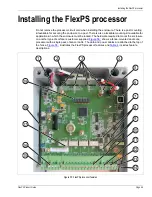


Installing the sensor cable
FlexPS Product Guide
Page 39
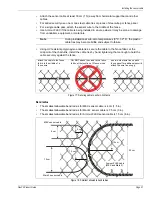
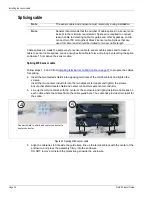
Installation at a sliding gate on the outside of the perimeter
Secure the lead-in cables to the cable guide bar (L-bracket) to prevent the cables from becoming
jammed between the gate and the fence when the gate is opened.
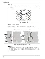
Gate disconnect assembly
The gate disconnect assembly protects gates that are infrequently used. The gate can be opened
and closed by manually separating the connection. When the assembly is opened, a supervision
alarm is generated. When the assembly is closed the gate is protected and secure.
Note
It may be necessary to install an L-bracket as a cable guide
bar, to prevent the cable from being jammed between the gate
and the fence panel.
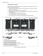
Figure 39: Sliding gate on outside of perimeter
3
4
5
2
1
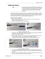
splice kits (X 5)
2 bundled lead-in cables
bundled lead-in cables secured to gate
bypass cable
bundled lead-in cables
gate closed
gate open
Connection details
1. Sensor cable on fence to lead-in cable to gate.
2. Lead-in cable to gate to sensor cable on gate.
3. Sensor cable on gate to lead-in cable to fence.
4. Lead-in cable from gate to bypass cable to other side of gate.
5. Bypass cable to sensor cable on other side of fence.
cable guide bar
direction to open
secure bundled cables to gate
at this point only
at this point only
Содержание FlexPS
Страница 6: ...Page 6 FlexPSProduct Guide ...
Страница 66: ...Installing the FlexPS processor Page 66 FlexPS Product Guide ...
Страница 88: ...Page 88 FlexPS Product Guide ...
Страница 94: ...Page 94 FlexPS Product Guide ...