


Installing the sensor cable
Page 34
FlexPS Product Guide
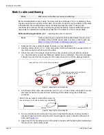
Splicing cable
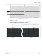
Cable splices are made the same way for sensor cable to sensor cable splices and for lead-in
cable to sensor cable splices. Leave enough extra cable to form a drip loop by elevating the splice
enclosure 15 cm above the sensor cable.
Splicing MEX sensor cable
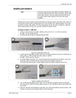
Follow steps 1, 2 and 3 from
Installing terminators on MEX cable on page 31
to prepare the cables
for splicing.
4.
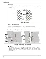
Insert the two twisted shields into opposing terminals of the terminal block and tighten the
screws.
Insert the two center conductors into the two adjacent terminals and tighten the screws.
Ensure that shield meets shield and center conductor meets center conductor.
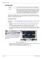
5.
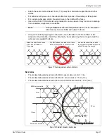
Line up the terminal block with the center of the enclosure and tightly install two cable ties on
each cable where the cables fit into the cable guide bars. The cable ties provide strain relief for
the splice.
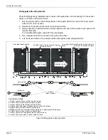
6.
Align the cable ties to fit beside the guide bars, line up the terminal block with the center of the
enclosure, and press the assembly firmly into the enclosure.
DO NOT remove or disturb the protective gel inside the enclosure.
Note
The sensor cable and enclosure must remain dry during installation.
Note
Senstar recommends that the number of cable splices in a sensor zone
be kept to the minimum requirement. Splices are required to connect
lead-in cable to detecting cable, for gates and other bypasses, and to
connect two 150 m lengths of Mark 2 sensor cable. Splices that are
used for cable repair should be limited to two per cable length.
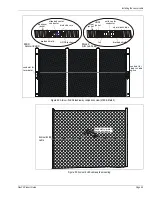
Figure 32: Splicing MEX sensor cable
4
5
Connect shield to shield and center conductor to
center conductor.
Содержание FlexPS
Страница 6: ...Page 6 FlexPSProduct Guide ...
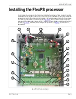
Страница 66: ...Installing the FlexPS processor Page 66 FlexPS Product Guide ...
Страница 88: ...Page 88 FlexPS Product Guide ...
Страница 94: ...Page 94 FlexPS Product Guide ...