


Installing the FlexPS processor
Page 50
FlexPS Product Guide
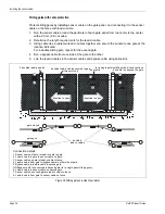
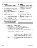
Free-standing or fence post mounting the enclosure
•
Install the processor near eye-level on the secure side of the perimeter.
•
Mount the enclosure with the cable entry holes on the bottom toward the ground.
•
Install an approved earth ground at the processor location.
•
Mounting the enclosure away from the protected fence on the secure side of the perimeter can
prevent tampering.
•
If razor ribbon is installed along the bottom of the fence, mount the processor on the secure
side of the perimeter, away from the fence and razor ribbon.
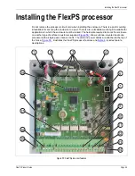
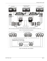
Item
Description
Item Description
1
T5 - 6 VDC rechargeable battery connector
11
T10 (terminals 1 & 2) - Flex Channel A sensor
cable input (- = shield, + = center conductor)
2
Tamper switch - open = tamper alarm
12
T10 (terminals 3 & 4) - Flex Channel B sensor
cable input (- = shield, + = center conductor)
3
Activity LEDs - door open, UCM active, network
power fail, internal power fail, battery fail, boot fail,
memory fail, TXA, RXA, fault A, TXB, RXB, fault B
(LED ON = condition active)
13
T10 (terminals 5 & 6) - Flex audio output
Connect an amplified speaker to use the audio
listen-in feature
4
Network interface card mounting hardware (X 2)
14
PCB ground strap
5
T1 - tamper input
15
T4 - power input (- +) 12 to 48 VDC
6
T3 - USB connection to UCM PC
16
Auxiliary inputs (self-test/audio activation/
auxiliary device inputs) AUX 1 - +, AUX 2 - +
7
UCM activity LEDs (TX, RX)
17
Relay activity LEDs (X4) - LED ON = relay
active
8
T6, T15, T7 - Channel A cable selection jumper
T14, T16, T11 - Channel B cable selection jumper
Place shunt on LOOSE for Mark 2 sensor cable
Place shunt on FIXED for MEX sensor cable
18
Input power LED - LED ON indicates an input
power problem
(voltage/current too high/low)
9
T12 - Channel A cable termination bypass jumper
T13 - Channel B cable termination bypass jumper
Remove the shunt if a properly terminated sensor
cable is connected to the corresponding input
19
T2 - Expansion header for network interface
card
10
T9 - Form C relay output connections (X4)
Normally Closed, Common, Normally Open
Table 4 Processor features
CAUTION
For installations in environments which include hot sunny periods,
Senstar recommends that a sun shield be installed to protect the
enclosure from direct sunlight, or that the enclosure be installed in a
shady area. The maximum operating temperature, as measured
inside the enclosure, is 70º C (158º F).
Tip
A 5/16 in. nut driver and a cordless drill will facilitate post mounting
the processor.
Содержание FlexPS
Страница 6: ...Page 6 FlexPSProduct Guide ...
Страница 66: ...Installing the FlexPS processor Page 66 FlexPS Product Guide ...
Страница 88: ...Page 88 FlexPS Product Guide ...
Страница 94: ...Page 94 FlexPS Product Guide ...