16
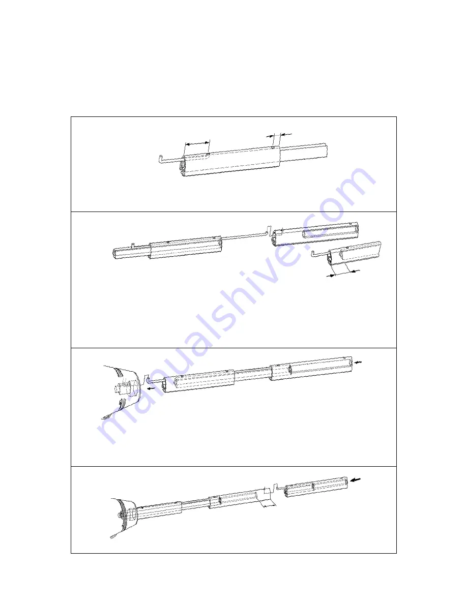
Insert one end of a 144 mm (5 11/16”) spring in the upper hole of the
1000 mm extrusion, and slide the long joining sleeve up to hold it in
place. Remove the 200 mm (7 7/8”) joining sleeve from a 2400 mm (94 1/2 ”) extrusion.
This will be used later in the 2000 mm (78 3/4”) extrusion. Connect the 2400 mm extrusion and
the 1000 mm extrusion. Push the long joining sleeve up into the 2400 mm extrusion to secure the
connection spring. Continue pushing until the bottom of the sleeve is 50mm inside lower end of
the 1000 mm extrusion. A 50 mm (2”) gap is formed at this joint (as shown in fig. 4.1.c.), where
the sail feeder is to be fitted later.
Fit the short connecting spring (L=103 mm/4 1/8”) to the 1000 mm (39 3/8”) extrusion. The larger
hook must be on the free end. Push the long joining sleeve (L=1168 mm/46”) down, to hold the
spring in place and make space for the next spring.
Connect the remaining extrusions as detailed in table 3.6.1.
Fig. 4.1.a
Fig. 4.1.c
Fig. 4.1.d
1.
2.
4.
3.
Assembly should be carried out on a horizontal surface. Connect the luff extrusions one by one,
starting at the lower bearing assembly.
90 mm (3 9/16”)
20 mm (13/16”)
The extrusions are then fitted to the adapter of the lower bearing assembly. Hook the connecting
spring to the internal hole in the adapter. Then push the distance tube in the 2400 mm extrusion
down so that the joining sleeve bottoms in the adapter. The distance tube should be buried
approximately 100 mm (4”), about equal to half a length of a joining sleeve.
≈ 50 mm
(≈2”)
≈ 100 mm (≈2”)
Fig. 4.1.b
4 Assembly of the Furlex System
4.1 Assembly of the luff section


