44
7.2 Continuous wire welding (MIG/MAG)
Introduction
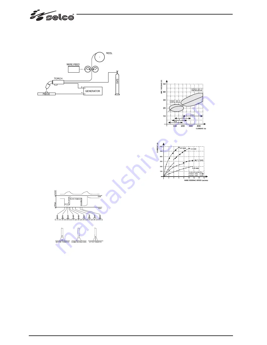
A MIG system consists of a direct current power source, wire
feeder, wire spool, torch and gas.
MIG manual welding system
The current is transferred to the arc through the fusible elec-
trode (wire connected to positive pole); in this procedure the
melted metal is transferred onto the workpiece through the arc
stream. The automatic feeding of the continuous filler material
electrode (wire) is necessary to refill the wire that has melted
during welding.
Methods
In MIG welding, two main metal transfer mechanisms are present
and they can be classified according to the means by which
metal is transferred from the electrode to the workpiece. The first
one, defined “SHORT-ARC”, produces a small, fast-solidifying
weld pool where metal is transferred from the electrode to the
workpiece only for a short period when the electrode is in con-
tact with the weld pool. In this timeframe, the electrode comes
into direct contact with the weld pool generating a short circuit
that melts the wire which is therefore interrupted. The arc then
turn on again and the cycle is repeated (Fig. 1a).
SHORT cycle (a) and SPRAY ARC welding (b)
Another mechanism for metal transfer is called the “SPRAY-ARC”
method, where the metal transfer occurs in the form of very small
drops that are formed and detached from the tip of the wire and
transferred to the weld pool through the arc stream (Fig. 1b).
Welding parameters
The visibility of the arc reduces the need for the user to strictly
observe the adjustment tables as he can directly monitor the
weld pool.
- The voltage directly affects the appearance of the bead, but
the dimensions of the weld bead can be varied according to
requirements by manually moving the torch to obtain variable
deposits with constant voltage.
- The wire feeding speed is proportional to the welding cur-
rent.
Fig. 2 and 3 show the relationships between the various welding
parameters.
Fig.2 Diagram for selection the of best working characteristic.
Fig.3 Relationship between wire feeding speed and current
amperage (melting characteristic) according to wire diameter.
Fig. 1a
Fig. 1b
Содержание Quasar 320 SMC Classic
Страница 94: ...94...
Страница 253: ...1 1 1 10 C 40 C 14 F 104 F 25 C 55 C 13 F 131 F 50 40 C 40 00 C 90 20 C 68 F 2000 6500 1 2 10 MIG MAG 253...
Страница 254: ...254 1 3 1 4 11 35 1 5...
Страница 255: ...255 1 6 1 7 EN IEC 60974 10 B A A EN60974 10 A pace maker Zmax Ssc Point of Commom Coupling PCC...
Страница 256: ...1 8 IP S IP23S 12 5 mm 60 2 2 1 2 2 10 2 3 400V 15 15 2 1 5 256...
Страница 257: ...257 2 4 MMA 1 2 3 4 MIG MAG MIG MAG 1 2 3 4 4 5 6 5 20...
Страница 268: ...268 5 6 Reset encoder...
Страница 269: ...269...
Страница 270: ...270...
Страница 271: ...271 7 7 1 MMA Hot Start Arc Force antisticking 7 2 MIG MAG MIG...
Страница 272: ...SHORT ARC 1a SHORT a SPRAY ARC b SPRAY ARC 1b 2 3 2 3 272 1a 1b...
Страница 278: ...278 QUASAR 320 SMC Exclusive...
Страница 279: ...279 QUASAR 400 SMC Classic Smart...
Страница 280: ...280 QUASAR 400 SMC Exclusive...
Страница 281: ...281...
Страница 283: ...283 Quasar 400 SMC Classic Smart Quasar 400 SMC Exclusive...
Страница 287: ...287...
Страница 288: ...288 55 15 004 55 15 005 55 15 006 QUASAR 400 SMC CLASSIC QUASAR 400 SMC SMART QUASAR 400 SMC EXCLUSIVE...
Страница 291: ...291...
Страница 295: ...295 73 11 012 Kit Push Pull...
Страница 296: ...296 2X M3 5x9mm...


