


RTC – 4553AC
Page - 15
MQ - 342 - 01
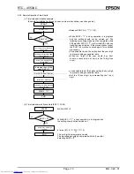
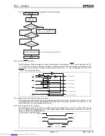
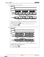
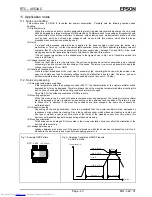
(7) Time/calendar read example using BUSY bit down transition
Read time/calendar
PONC=0?
Time and calendar read interval is 996 ms.
END
YES
YES
PONC=0?
NO
NO
NO
BUSY = 1?
START
If PONC = "1", initialization was
carried out and data must be set
again
MS
0
←
0
MS
1
←
0
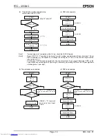
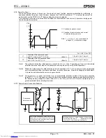
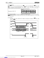
8.3.6. CS1 and CS0 Operation
When designing a floating arrangement, take the following into consideration. CS0 can be floating while CS1
= "L", but CS1 can never be floating. (Otherwise a through current would flow, leading to increased current
consumption during operation on backup battery power.) When CS1 = "L", input is disabled, and S
OUT
and
TP
OUT
are at high impedance.
To internal circuits
To internal circuits
To internal circuits
To internal circuits
From internal circuits
From internal circuits
CS
1
CS
0
WR
SCK
S
IN
S
OUT
TP
OUT
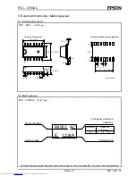
8.3.7. System Power Down During Interface Operation
When the system power goes down during interface operation with the CPU, causing CS1 to become "L", the
incomplete data will be invalid. Immediately after system power restoration, when CS1 has become "H", the
output data from S
OUT
are undefined for one cycle.
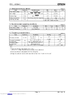
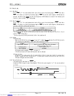
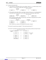
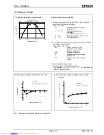
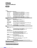
8.3.8. Power Supply and CS1 Operation
When the system power is shut down, V
DD
falls to the battery voltage. When used at V
DD
±10%, CS1 must be
set to "L" before V
DD
crosses point <A> in the diagram below. When system power is restored, CS1 must be
set to "H" before V
DD
crosses point <B>.
System power on/off time chart
System power
Access disabled
Power down
Battery voltage
<A> V
DD
-20 %
<B>
CS
1
V
DD
5 V
electronic components distributor


