


ELECTRICAL SYSTEM
14 -
34
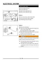
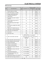
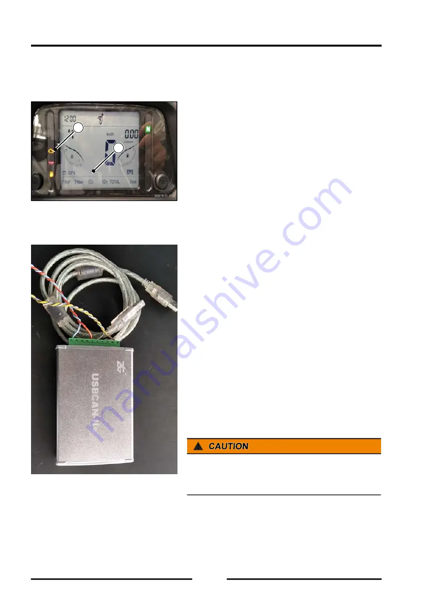
Fault code reading
There is a fault indicator (
【
A
】
in the left figure) in the
instrument. When the key switch is turned on, the fault
indicator is always on. When the engine is running, if the
vehicle electronically controlled fuel injection system has
no faults, the indicator light should go out; if there is a
fault, the indicator light should always be on, indicating
that the system is faulty. The indicator (
【
B
】
in the
left figure) can display the relevant fault code, and the
specifi c fault information can be queried through the fault
code summary table.
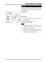
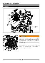
Troubleshooter operation
When the engine is running, the instrument fault indicator
is always on, indicating that the system is faulty. At
present, use a dedicated fault diagnosis instrument
(bottom left) to read the corresponding fault information.
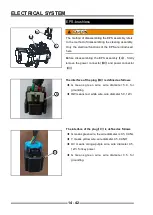
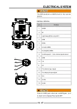
Use the OBD diagnostic interface to connect to the
corresponding diagnostic interface of the vehicle, and
connect the other end of the device to the computer
(diagnostic software and corresponding drivers should be
installed on the computer), and the key switch should be
turned on. Specifi c steps:
◆
Connect the device, select "Open CAN", and press
the OK button.
◆
Enter the main interface, you can view engine
operating parameters and fault information
!
When the engine is not running, it is normal that the
fault light is always on, and there is no need to deal with
it
A
B
Содержание SNARLER ATV 2021 Series
Страница 1: ...SERVICE MANUAL ATV SERIES PRODUCTS 20210804 V01...
Страница 39: ...ENGINE LUBRICATION SYSTEM ENGINE LUBRICATION SYSTEM 3 1 2 Exploded view...
Страница 99: ...ENGINE COOLING SYSTEM ENGINE COOLING SYSTEM 3 4 2 Exploded view...
Страница 120: ...ENGINE TOP END ENGINE TOP END 3 5 10 Spark Plug Valve Cover Throttle Body Camshaft...
Страница 153: ...CVT SYSTEM CVT SYSTEM 3 6 2 L L G G G G R R Lh Lh R R R R Exploded view...
Страница 155: ...CVT SYSTEM CVT SYSTEM 3 6 4 R R R R G G R R L L Lh Lh M M G G G G G G...
Страница 185: ...4 13 FRONT AND REAR DIFFERENTIAL FRONT AND REAR DIFFERENTIAL...
Страница 212: ...COOLING SYSTEM 6 6 Special tools and sealants Silicone Sealant...
Страница 230: ...FRONT REAR SUSPENSION 9 2 Exploded view of Front suspension...
Страница 232: ...FRONT REAR SUSPENSION 9 4 Exploded view of Rear suspension...
Страница 246: ...WHEELS AND TIRES 10 2 Exploded view of Wheels and Tires R W R 1 2 5 6 5 6 7 R R R R R W 1 2 3 3 4 3 7 4...
Страница 249: ...WHEELS AND TIRES 10 5 Special Tools Jack...
Страница 264: ...BRAKE SYSTEM 11 5 Inside Circlip Pliers Special tool...
Страница 276: ...STEERING SYSTEM 12 2 Exploded View of Steering System 1 2 A A 3 4 5 5 5 6 3 B...
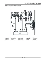
Страница 323: ...ELECTRICAL SYSTEM 14 15 EFI system Schematic diagram of EFI system...
Страница 383: ...ELECTRICAL SYSTEM 14 75 B10 B11 B12 B14 B15 B16...
Страница 386: ...ELECTRICAL SYSTEM 14 78 Wiring diagram...