


ELECTRICAL SYSTEM
14 -
28
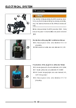
Engine speed sensor
The working principle of the speed sensor is to use the
magnetoelectric eff ect. When the shaft rotates, the signal
wheel is driven to rotate together, and the teeth on the
signal wheel will cut the magnetic line of the sensor. This
change in magnetic flux causes a certain frequency at
both ends of the sensor coil. The output voltage is output
to the electronic controller, and the output signal can
represent the crankshaft speed and position (see A in the
fi gure below).
Technical performance test
The speed sensor outputs a sinusoidal voltage signal,
and the output signal (see
【
B
】
on the left)
Coil resistance (23
℃
) : 950-20 Ω
Coil inductance (1000HZ) : 450±15 mH
Fault diagnosis
◆
When the engine cannot be started,the remaining
fault points have been eliminated. Use a multimeter
to test whether the coil resistance of the speed
sensor is the resistance required by the technical
performance.
◆
If the resistance value is normal, please use an
oscilloscope to check whether the voltage signal
output by the sensor is as shown in the fi gure (B in
the left fi gure)
!
When the two pins of the sensor are connected
reversely, the fi rst gear signal after the missing gear in
the output voltage signal is negative, which will cause
the engine to be turbulent, idling unstable or unable to
start.
A
B
Содержание SNARLER ATV 2021 Series
Страница 1: ...SERVICE MANUAL ATV SERIES PRODUCTS 20210804 V01...
Страница 39: ...ENGINE LUBRICATION SYSTEM ENGINE LUBRICATION SYSTEM 3 1 2 Exploded view...
Страница 99: ...ENGINE COOLING SYSTEM ENGINE COOLING SYSTEM 3 4 2 Exploded view...
Страница 120: ...ENGINE TOP END ENGINE TOP END 3 5 10 Spark Plug Valve Cover Throttle Body Camshaft...
Страница 153: ...CVT SYSTEM CVT SYSTEM 3 6 2 L L G G G G R R Lh Lh R R R R Exploded view...
Страница 155: ...CVT SYSTEM CVT SYSTEM 3 6 4 R R R R G G R R L L Lh Lh M M G G G G G G...
Страница 185: ...4 13 FRONT AND REAR DIFFERENTIAL FRONT AND REAR DIFFERENTIAL...
Страница 212: ...COOLING SYSTEM 6 6 Special tools and sealants Silicone Sealant...
Страница 230: ...FRONT REAR SUSPENSION 9 2 Exploded view of Front suspension...
Страница 232: ...FRONT REAR SUSPENSION 9 4 Exploded view of Rear suspension...
Страница 246: ...WHEELS AND TIRES 10 2 Exploded view of Wheels and Tires R W R 1 2 5 6 5 6 7 R R R R R W 1 2 3 3 4 3 7 4...
Страница 249: ...WHEELS AND TIRES 10 5 Special Tools Jack...
Страница 264: ...BRAKE SYSTEM 11 5 Inside Circlip Pliers Special tool...
Страница 276: ...STEERING SYSTEM 12 2 Exploded View of Steering System 1 2 A A 3 4 5 5 5 6 3 B...
Страница 323: ...ELECTRICAL SYSTEM 14 15 EFI system Schematic diagram of EFI system...
Страница 383: ...ELECTRICAL SYSTEM 14 75 B10 B11 B12 B14 B15 B16...
Страница 386: ...ELECTRICAL SYSTEM 14 78 Wiring diagram...


