


ENGINE TOP END
ENGINE TOP END
3-5-37
A
A
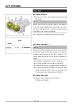
Timing View For Camshafts
Timing View For Sprockets
A
A
B
B
C
C
D
D
IMPORTANT
IMPORTANT
:
:
Always inspect valve clearance prior to
camshaft installation or fi nal engine assembly.
◆
Camshaft installation
installation (See the Camshaft Installation
Camshaft Installation
/ Timing
/ Timing)
◆
Camshaft Carrier installation (See the Camshaft
Camshaft
Installation / Timing
Installation / Timing)
◆
Rotate the camshaft until the cam lobes
【
C
】
and
【
D
】
above the valves you are inspecting are facing
up.
◆
Measure the valve clearance
【
A
】
and
【
B
】
using a
thickness (feeler) gauge. Record the measurement if
clearance is out of specifi cation.
◆
Repeat the above steps until all four valves have
been inspected.
Measurement Valve Clearance (cold)
Exhaust:
0.2 ~ 0.3mm (0.0080" ~ 0.0120")
Inlet:
0.1 ~ 0.2mm (0.0040" ~ 0.0080")
If any of the valve clearance measurements are out
of specification, remove the camshaft carriers and
camshafts and proceed with this procedure.
CAUTION
CAUTION
If all valve clearance measurements are within
specifi cation, remove the camshaft carriers and proceed
to Camshaft Installation
◆
Remove the valve tappet from a valve that was out
of specifi cation.
CAUTION
CAUTION
Keep mated parts together and in order with respect
to their location in the cylinder head for assembly
purposes. Mark each component or place them in an
organized rack as you remove them.
Valve Clearance Adjustment
Содержание SNARLER ATV 2021 Series
Страница 1: ...SERVICE MANUAL ATV SERIES PRODUCTS 20210804 V01...
Страница 39: ...ENGINE LUBRICATION SYSTEM ENGINE LUBRICATION SYSTEM 3 1 2 Exploded view...
Страница 99: ...ENGINE COOLING SYSTEM ENGINE COOLING SYSTEM 3 4 2 Exploded view...
Страница 120: ...ENGINE TOP END ENGINE TOP END 3 5 10 Spark Plug Valve Cover Throttle Body Camshaft...
Страница 153: ...CVT SYSTEM CVT SYSTEM 3 6 2 L L G G G G R R Lh Lh R R R R Exploded view...
Страница 155: ...CVT SYSTEM CVT SYSTEM 3 6 4 R R R R G G R R L L Lh Lh M M G G G G G G...
Страница 185: ...4 13 FRONT AND REAR DIFFERENTIAL FRONT AND REAR DIFFERENTIAL...
Страница 212: ...COOLING SYSTEM 6 6 Special tools and sealants Silicone Sealant...
Страница 230: ...FRONT REAR SUSPENSION 9 2 Exploded view of Front suspension...
Страница 232: ...FRONT REAR SUSPENSION 9 4 Exploded view of Rear suspension...
Страница 246: ...WHEELS AND TIRES 10 2 Exploded view of Wheels and Tires R W R 1 2 5 6 5 6 7 R R R R R W 1 2 3 3 4 3 7 4...
Страница 249: ...WHEELS AND TIRES 10 5 Special Tools Jack...
Страница 264: ...BRAKE SYSTEM 11 5 Inside Circlip Pliers Special tool...
Страница 276: ...STEERING SYSTEM 12 2 Exploded View of Steering System 1 2 A A 3 4 5 5 5 6 3 B...
Страница 323: ...ELECTRICAL SYSTEM 14 15 EFI system Schematic diagram of EFI system...
Страница 383: ...ELECTRICAL SYSTEM 14 75 B10 B11 B12 B14 B15 B16...
Страница 386: ...ELECTRICAL SYSTEM 14 78 Wiring diagram...


