


ENGINE TOP END
ENGINE TOP END
3-5-25
JJ
F
F
E
E
D
D
G
G
H
H
A
A
B
B
C
C
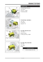
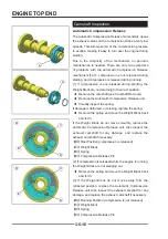
[F] Good
[G] Too Wide
[H] Too Narrow
[J] Uneven
Valve Seating Surface Width
Exhaust: 1.5 ~ 1.6mm (0.0591" ~ 0.0630")
Inlet:
1.0 ~ 1.1mm (0.0394" ~ 0.0433")
Valve Seat Reconditioning
Valve Seat Reconditioning
◆
Valve seat reconditioning should be performed by a
technician profi cient in cylinder head reconditioning
techniques. Reconditioning techniques vary,
so follow the instructions provided by the valve
reconditioning equipment manufacturer. Do not
grind seats more than necessary to provide proper
seat surface, width, and contact point on valve face.
!
WARNING
WARNING
Wear eye protection or a face shield during cylinder
head disassembly and reassembly.
Valve Seat Inspection:
Valve Seat Inspection:
◆
Remove the valve (see Valve Removal).
◆
Check the valve seating surface
【
A
】
between the
valve
【
B
】
and valve seat
【
C
】
.
Coat the valve seat with machinist’s dye.
Push the valve into the guide.
Rotate the valve against the seat with a lapping tool.
Pull the valve out, and check the seating pattern on the
valve head. It must be the correct width and even all the
way around.
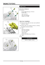
◆
Measure the outside diameter
【
D
】
of the seating
pattern on the valve seat.
If the outside diameter of the valve seating pattern is
too large or too small, repair the seat (see Valve Seat
Repair).
Valve Seating Surface Outside Diameter:
Exhaust:
31.8 ~ 31.9 mm (1.2520" ~ 1.2559")
Inlet:
36.8 ~ 36.9 mm (1.4488" ~ 1.4528")
NOTE
NOTE
The valve stem and guide must be in good condition, or
this check will not be valid.
If the valve seating pattern is not correct, repair the seat
(see Valve Seat Repair).
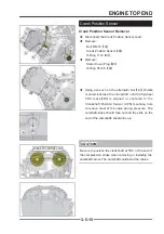
◆
Measure the seat width
【
E
】
of the portion where
there is no build-up carbon (white portion) of the
valve seat with vernier calipers.
If the width is too wide, too narrow or uneven, repair the
seat (see Valve Seat Repair).
Содержание SNARLER ATV 2021 Series
Страница 1: ...SERVICE MANUAL ATV SERIES PRODUCTS 20210804 V01...
Страница 39: ...ENGINE LUBRICATION SYSTEM ENGINE LUBRICATION SYSTEM 3 1 2 Exploded view...
Страница 99: ...ENGINE COOLING SYSTEM ENGINE COOLING SYSTEM 3 4 2 Exploded view...
Страница 120: ...ENGINE TOP END ENGINE TOP END 3 5 10 Spark Plug Valve Cover Throttle Body Camshaft...
Страница 153: ...CVT SYSTEM CVT SYSTEM 3 6 2 L L G G G G R R Lh Lh R R R R Exploded view...
Страница 155: ...CVT SYSTEM CVT SYSTEM 3 6 4 R R R R G G R R L L Lh Lh M M G G G G G G...
Страница 185: ...4 13 FRONT AND REAR DIFFERENTIAL FRONT AND REAR DIFFERENTIAL...
Страница 212: ...COOLING SYSTEM 6 6 Special tools and sealants Silicone Sealant...
Страница 230: ...FRONT REAR SUSPENSION 9 2 Exploded view of Front suspension...
Страница 232: ...FRONT REAR SUSPENSION 9 4 Exploded view of Rear suspension...
Страница 246: ...WHEELS AND TIRES 10 2 Exploded view of Wheels and Tires R W R 1 2 5 6 5 6 7 R R R R R W 1 2 3 3 4 3 7 4...
Страница 249: ...WHEELS AND TIRES 10 5 Special Tools Jack...
Страница 264: ...BRAKE SYSTEM 11 5 Inside Circlip Pliers Special tool...
Страница 276: ...STEERING SYSTEM 12 2 Exploded View of Steering System 1 2 A A 3 4 5 5 5 6 3 B...
Страница 323: ...ELECTRICAL SYSTEM 14 15 EFI system Schematic diagram of EFI system...
Страница 383: ...ELECTRICAL SYSTEM 14 75 B10 B11 B12 B14 B15 B16...
Страница 386: ...ELECTRICAL SYSTEM 14 78 Wiring diagram...