


ELECTRICAL SYSTEM
14 -
29
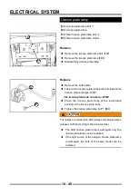
Oil Pressure Sensor
The oil pressure sensor detects the size of the engine oil
pressure when it is working, and it is usually screwed into
the oil passage of the cylinder block. Its working principle
is that there is a variable resistor inside the sensor, one
end outputs the signal, and the other end is connected
to the grounded sliding arm. When the oil pressure
increases, the oil pressure pushes the diaphragm
through the lubricating oil channel interface to bend, and
the diaphragm pushes the sliding arm to a low resistance
position, which increases the output current in the circuit,
and vice versa, reduces the output current in the circuit.
(See
【
A
】
in the fi gure below). The sensor is a normally
open contact, the working pressure is 250±10kPa,
and the maximum working temperature is greater than
150°C. When the oil pressure is too low, the oil pressure
indicator on the instrument is always on.
A
Fault diagnosis
◆
When there is no oil pressure indicator, it is
generally because the wiring harness connector is
poorly connected.
◆
When the wiring harness connect or is well
connect ed, the sensor itself is fault y. I t is
recommended to replace the sensor with a new one.
!
When an oil pressure failure occurs, you must
troubleshoot the failure. Forcible operation will damage
the engine.
Содержание SNARLER ATV 2021 Series
Страница 1: ...SERVICE MANUAL ATV SERIES PRODUCTS 20210804 V01...
Страница 39: ...ENGINE LUBRICATION SYSTEM ENGINE LUBRICATION SYSTEM 3 1 2 Exploded view...
Страница 99: ...ENGINE COOLING SYSTEM ENGINE COOLING SYSTEM 3 4 2 Exploded view...
Страница 120: ...ENGINE TOP END ENGINE TOP END 3 5 10 Spark Plug Valve Cover Throttle Body Camshaft...
Страница 153: ...CVT SYSTEM CVT SYSTEM 3 6 2 L L G G G G R R Lh Lh R R R R Exploded view...
Страница 155: ...CVT SYSTEM CVT SYSTEM 3 6 4 R R R R G G R R L L Lh Lh M M G G G G G G...
Страница 185: ...4 13 FRONT AND REAR DIFFERENTIAL FRONT AND REAR DIFFERENTIAL...
Страница 212: ...COOLING SYSTEM 6 6 Special tools and sealants Silicone Sealant...
Страница 230: ...FRONT REAR SUSPENSION 9 2 Exploded view of Front suspension...
Страница 232: ...FRONT REAR SUSPENSION 9 4 Exploded view of Rear suspension...
Страница 246: ...WHEELS AND TIRES 10 2 Exploded view of Wheels and Tires R W R 1 2 5 6 5 6 7 R R R R R W 1 2 3 3 4 3 7 4...
Страница 249: ...WHEELS AND TIRES 10 5 Special Tools Jack...
Страница 264: ...BRAKE SYSTEM 11 5 Inside Circlip Pliers Special tool...
Страница 276: ...STEERING SYSTEM 12 2 Exploded View of Steering System 1 2 A A 3 4 5 5 5 6 3 B...
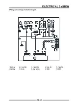
Страница 323: ...ELECTRICAL SYSTEM 14 15 EFI system Schematic diagram of EFI system...
Страница 383: ...ELECTRICAL SYSTEM 14 75 B10 B11 B12 B14 B15 B16...
Страница 386: ...ELECTRICAL SYSTEM 14 78 Wiring diagram...


