


ENGINE TOP END
ENGINE TOP END
3-5-23
B
B
D
D
E
E
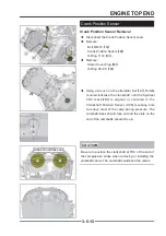
◆
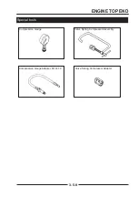
Measure the free length of each valve spring with a
Vernier caliper and compare to specifi cation.
◆
Valve Spring Free Length: Standard: 1.726" (43.85
mm)Service Limit: 1.683" (42.75 mm)
Standard
Service Limit
42.5 mm (1.6732")
41.4mm (1.6299")
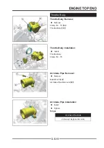
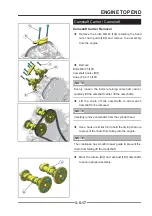
Valve Guide / Valve Inspection
Valve Guide / Valve Inspection
◆
Valve-to-Guide Clearance Measurement:
If a small bore gauge is not available, inspect the valve
guide wear by measuring the valve to valve guide
clearance with the wobble method as indicated below.
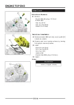
◆
Insert a new valve
【
A
】
into the guide
【
B
】
and
set a dial gauge against the stem perpendicular to
it as close as possible to the cylinder head mating
surface.
◆
Move
【
C
】
the stem back and forth to measure
valve/valve guide clearance.
◆
Repeat the measurement in a direction at a right
angle to the fi rst.
If the reading exceeds the service limit, replace the
Cylinder head & Camshaft Carrier Combination.
NOTE
NOTE
The reading is not actual valve/valve guide clearance
because the measuring point is above the guide.
Valve/Valve Guide Clearance (Wobble Method)
Standard
Service Limit
Exhaust:
0.09 ~ 0.17 mm
(0.0035" ~ 0.0067")
0.34 mm
0.0133"
Inlet:
0.03 ~ 0.11 mm
(0.0012" ~ 0.0043")
0.28 mm
0.0110"
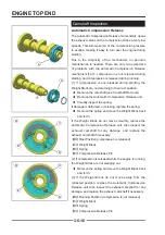
◆
Check valve face for runout, pitting, and burnt spots.
To check for bent valve stems, mount valve in a drill
or use “V” blocks and a dial indicator.
◆
Check the end of the valve stem for fl aring, pitting,
wear or damage.
◆
Inspect split keeper groove for wear or fl aring in the
keeper seat area.
Содержание SNARLER ATV 2021 Series
Страница 1: ...SERVICE MANUAL ATV SERIES PRODUCTS 20210804 V01...
Страница 39: ...ENGINE LUBRICATION SYSTEM ENGINE LUBRICATION SYSTEM 3 1 2 Exploded view...
Страница 99: ...ENGINE COOLING SYSTEM ENGINE COOLING SYSTEM 3 4 2 Exploded view...
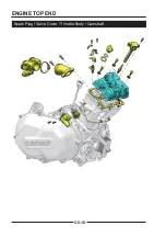
Страница 120: ...ENGINE TOP END ENGINE TOP END 3 5 10 Spark Plug Valve Cover Throttle Body Camshaft...
Страница 153: ...CVT SYSTEM CVT SYSTEM 3 6 2 L L G G G G R R Lh Lh R R R R Exploded view...
Страница 155: ...CVT SYSTEM CVT SYSTEM 3 6 4 R R R R G G R R L L Lh Lh M M G G G G G G...
Страница 185: ...4 13 FRONT AND REAR DIFFERENTIAL FRONT AND REAR DIFFERENTIAL...
Страница 212: ...COOLING SYSTEM 6 6 Special tools and sealants Silicone Sealant...
Страница 230: ...FRONT REAR SUSPENSION 9 2 Exploded view of Front suspension...
Страница 232: ...FRONT REAR SUSPENSION 9 4 Exploded view of Rear suspension...
Страница 246: ...WHEELS AND TIRES 10 2 Exploded view of Wheels and Tires R W R 1 2 5 6 5 6 7 R R R R R W 1 2 3 3 4 3 7 4...
Страница 249: ...WHEELS AND TIRES 10 5 Special Tools Jack...
Страница 264: ...BRAKE SYSTEM 11 5 Inside Circlip Pliers Special tool...
Страница 276: ...STEERING SYSTEM 12 2 Exploded View of Steering System 1 2 A A 3 4 5 5 5 6 3 B...
Страница 323: ...ELECTRICAL SYSTEM 14 15 EFI system Schematic diagram of EFI system...
Страница 383: ...ELECTRICAL SYSTEM 14 75 B10 B11 B12 B14 B15 B16...
Страница 386: ...ELECTRICAL SYSTEM 14 78 Wiring diagram...