


ENGINE TOP END
ENGINE TOP END
3-5-26
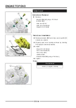
Valve Seat Repair (Valve Lapping)
Valve Seat Repair (Valve Lapping)
◆
Install pilot into valve guide.
◆
Apply cutting oil to valve seat and cutter.
◆
Place 46° cutter on the pilot and make a light cut.
◆
Inspect the cut area of the seat:
If the contact area is less than 75% of the circumference
of the seat, rotate the pilot 180° and make another light
cut.
If the cutter now contacts the uncut portion of the seat,
check the pilot. Look for burrs, nicks, or runout. If the pilot
is bent it must be replaced.
If the contact area of the cutter is in the same place, the
valve guide is distorted from improper installation.
If the contact area of the initial cut is greater than 75%,
continue to cut the seat until all pits are removed and a
new seat surface is evident.
◆
To check contact area of the seat on the valve face,
apply a thin coating of Prussian Blue™ paste to the
valve seat. If using an interference angle (46°) apply
black permanent marker to the entire valve face
【
A
】
.
◆
Insert valve into guide and tap valve lightly into place
a few times.
◆
Remove valve and check where the Prussian Blue™
indicates seat contact on the valve face. The valve
seat should contact the middle of the valve face or
slightly above, and must be the proper width.
If the indicated seat contact is at the top edge of the valve
face and contacts the margin area
【
B
】
it is too high on
the valve face. Use the 30° cutter to lower the valve seat.
If too low, use the 60° cutter to raise the seat. When
contact area is centered on the valve face, measure seat
width.
If the seat is too wide or uneven, use both top and bottom
cutters to narrow the seat.
If the seat is too narrow, widen using the 45° cutter and
re-check contact point on the valve face and seat width
after each cut.
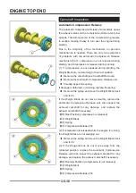
A
A
B
B
A
A
Proper Seat Contact
on Valve Face
Содержание SNARLER ATV 2021 Series
Страница 1: ...SERVICE MANUAL ATV SERIES PRODUCTS 20210804 V01...
Страница 39: ...ENGINE LUBRICATION SYSTEM ENGINE LUBRICATION SYSTEM 3 1 2 Exploded view...
Страница 99: ...ENGINE COOLING SYSTEM ENGINE COOLING SYSTEM 3 4 2 Exploded view...
Страница 120: ...ENGINE TOP END ENGINE TOP END 3 5 10 Spark Plug Valve Cover Throttle Body Camshaft...
Страница 153: ...CVT SYSTEM CVT SYSTEM 3 6 2 L L G G G G R R Lh Lh R R R R Exploded view...
Страница 155: ...CVT SYSTEM CVT SYSTEM 3 6 4 R R R R G G R R L L Lh Lh M M G G G G G G...
Страница 185: ...4 13 FRONT AND REAR DIFFERENTIAL FRONT AND REAR DIFFERENTIAL...
Страница 212: ...COOLING SYSTEM 6 6 Special tools and sealants Silicone Sealant...
Страница 230: ...FRONT REAR SUSPENSION 9 2 Exploded view of Front suspension...
Страница 232: ...FRONT REAR SUSPENSION 9 4 Exploded view of Rear suspension...
Страница 246: ...WHEELS AND TIRES 10 2 Exploded view of Wheels and Tires R W R 1 2 5 6 5 6 7 R R R R R W 1 2 3 3 4 3 7 4...
Страница 249: ...WHEELS AND TIRES 10 5 Special Tools Jack...
Страница 264: ...BRAKE SYSTEM 11 5 Inside Circlip Pliers Special tool...
Страница 276: ...STEERING SYSTEM 12 2 Exploded View of Steering System 1 2 A A 3 4 5 5 5 6 3 B...
Страница 323: ...ELECTRICAL SYSTEM 14 15 EFI system Schematic diagram of EFI system...
Страница 383: ...ELECTRICAL SYSTEM 14 75 B10 B11 B12 B14 B15 B16...
Страница 386: ...ELECTRICAL SYSTEM 14 78 Wiring diagram...