


BRAKE SYSTEM
11 -
12
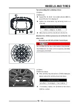
Brake Pads
Brake Pad Removal
◆
Remove front rim assembly or rear rim assembly
◆
Loosen the fasten blot from the guide rod of brake
assembly, during process of loosening the bolt,
the required head should always be in contact with
brake caliper body and limit, otherwise it will follow
because C is not limited, then it is impossible to
disassemble.
◆
Rotate the brake caliper at least 90 degrees, so that
the brake pad can be easily removed from spring
holder inside and outside of the brake disc.
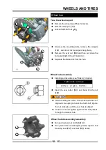
Brake Pad Installation
◆
Push the caliper piston in by hand as far as it will go.
◆
Be sure that the anti-rattle spring is in place.
◆
Install:
1. Install the brake pad in the upper and lower spring
holder on the inner or outer side, and fit the brake
disc respectively.
2. Rotate the brake caliper down so that the mounting
hole position coincides with the hole position of brake
assembly guide rod, and the brake assembly guide
rod must be confi ned to the brake caliper, and it fi ts
with brake caliper.
3. Apply thread glue to the newly loosened fastening
bolt
Torque - Fasten the fastening bolt
25N·m
(
2.5kgf·m
,
18ft·lb
)
!
Do not attempt to drive the vehicle until a firm brake
lever can be obtained by pumping the brake lever until
the pads are against each disc. The brake will not
function on the fi rst application if this is not done.
Brake Pad Wear Inspection
◆
Refer to the Brakes in the Periodic Maintenance
chapter.
A
D
B
C
E
Содержание SNARLER ATV 2021 Series
Страница 1: ...SERVICE MANUAL ATV SERIES PRODUCTS 20210804 V01...
Страница 39: ...ENGINE LUBRICATION SYSTEM ENGINE LUBRICATION SYSTEM 3 1 2 Exploded view...
Страница 99: ...ENGINE COOLING SYSTEM ENGINE COOLING SYSTEM 3 4 2 Exploded view...
Страница 120: ...ENGINE TOP END ENGINE TOP END 3 5 10 Spark Plug Valve Cover Throttle Body Camshaft...
Страница 153: ...CVT SYSTEM CVT SYSTEM 3 6 2 L L G G G G R R Lh Lh R R R R Exploded view...
Страница 155: ...CVT SYSTEM CVT SYSTEM 3 6 4 R R R R G G R R L L Lh Lh M M G G G G G G...
Страница 185: ...4 13 FRONT AND REAR DIFFERENTIAL FRONT AND REAR DIFFERENTIAL...
Страница 212: ...COOLING SYSTEM 6 6 Special tools and sealants Silicone Sealant...
Страница 230: ...FRONT REAR SUSPENSION 9 2 Exploded view of Front suspension...
Страница 232: ...FRONT REAR SUSPENSION 9 4 Exploded view of Rear suspension...
Страница 246: ...WHEELS AND TIRES 10 2 Exploded view of Wheels and Tires R W R 1 2 5 6 5 6 7 R R R R R W 1 2 3 3 4 3 7 4...
Страница 249: ...WHEELS AND TIRES 10 5 Special Tools Jack...
Страница 264: ...BRAKE SYSTEM 11 5 Inside Circlip Pliers Special tool...
Страница 276: ...STEERING SYSTEM 12 2 Exploded View of Steering System 1 2 A A 3 4 5 5 5 6 3 B...
Страница 323: ...ELECTRICAL SYSTEM 14 15 EFI system Schematic diagram of EFI system...
Страница 383: ...ELECTRICAL SYSTEM 14 75 B10 B11 B12 B14 B15 B16...
Страница 386: ...ELECTRICAL SYSTEM 14 78 Wiring diagram...


