background image

TB XRN2  02.00 E

19

5.2


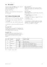
DIP switches

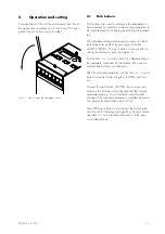
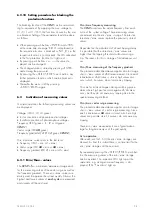
On the front plate of the 

XRN2

-relay there is one DIP

switch to preset the following functions:


Password programming


Output relay functions

The figure 3.1 shows the position and designation of
the code jumpers:

5.2.1


Function of the output relays

The following functions of the output relays can be pre-
set:


Alarm relay activation at pickup or after tripping
of the relay


Reset of the output relays manually or automatically

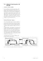
The alarm relays are activated according to the preset-
ting:

Dip switch 2 OFF:

The alarm relays pickup directly with energizing of the
corresponding measuring circuit. Thus, an alarm signal-
ling can be given before the relay trips.

Dip switch 2 ON:

The alarm relays pickup only after relay trip. That
means: the trip relay and the corresponding alarm re-
lay pickup at the same time after the time delay
elapsed.

Dip switch 3 OFF:

All output relays will be reset automatically after the
fault has been rectified, (e.g. when the fault current is
interrupted).

Dip switch 3 ON:

All output relays remains activated and must be reset af-
ter fault clearence.


Manually: By pressing push button
<SELECT/RESET>


External: By connecting aux. voltage to C2/C2L or
C2/C2H


Via RS 485 interface

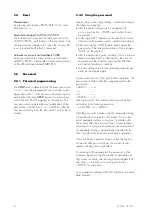
To let the parameter change take effect, the auxiliary
voltage has to be switched on and off again after the
dip switches are plugged or unplugged.

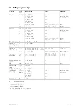
Dip switch

Function

Dip switch
position

Operation mode

1

Password

OFF

Normal position

ON

Password selection

2

Alarm relays

OFF

Alarm relays will be activated at pickup

ON

Alarm relay will be activated at tripping

3

Reset

OFF

Output relays will be reset automatically

ON

Output relays will be reset manual/external/via software

4

none

Table 5.1: Summary of coding possibilities

Содержание XRN2

Страница 1: ...XRN2 Mains decoupling relay ...

Страница 2: ...upervision 6 2 2 Setting of nominal frequency 6 2 3 Number of measuring repetitions T for frequency functions 6 2 4 Threshold of frequency supervision 6 2 5 Tripping delays for the frequency elements 6 2 6 Parameter setting of vector surge supervision XRN2 1 6 2 7 Parameter setting of frequency gradient XRN2 2 6 2 8 Voltage threshold value for frequency and vector surge measuring df dt at XRN2 2 6...

Страница 3: ... harmonics and d c components induced by faults or system op erations Integrated functions for voltage frequency and vector surge in one device as well as single voltage fre quency and vector surge devices Voltage supervision each with two step under and overvoltage detection Frequency supervision with three step under or overfrequency user setting Completely independent time settings for voltage ...

Страница 4: ... C1H the previously set relay functions are blocked refer to 4 8 and 6 2 10 3 1 3 Reset input Please refer to chapter 6 4 3 1 4 Output relays The XRN2 has 5 output relays One trip relay with two changeover contacts One alarm relay with two changeover contacts and three alarm relays with one changeover contact Tripping 11 12 14 and 21 22 24 Indication of over and undervoltage alarm 31 32 34 and 41 ...

Страница 5: ... values can be achieved by HTL PL Soft3 which will be provided on request to gether with the relay The XRN2 can be connected to other units of the PROFESSIONAL LINE via interface If there are more than one relay in the system the last relay of the chain has to be provided with a line termination resistor Fig 3 2 Connection example with 3 users XR as linked device Fig 3 3 Connection example with 3 ...

Страница 6: ...on elements The front plate of the XRN2 protection relay comprises the following operation and indication elements Alphanumerical display 4 Digits Push buttons for setting and other operations LEDs for measured value indication and setting Fig 3 4 Front plate XRN2 ...

Страница 7: ...e f2 tf2 frequency element f3 tripping delay of frequency element f3 setting value in Hz setting value in seconds SELECT RESET one time for each value f3 tf3 1 of 3 3 of 3 measurement 1Ph 3Ph SELECT RESET 1 3 XRN2 1 threshold for vector surge setting value in degree SELECT RESET Θ XRN2 1 setting value df dt measuring repitition df dt setting value in Hz s setting value in periods SELECT RESET one ...

Страница 8: ...he push button SELECT RESET are lit green during setting and inquiry procedure of the set ting values which are printed on the left side next to the LEDs The LEDs will light up red after activation of the setting values next to their right side The LED marked with letters RS lights up during setting of the slave address of the device for serial data com munication 3 2 4 Front plate XRN2 1 3 2 5 Fr...

Страница 9: ...ing parameter XRN2 1 XRN2 2 Y X X U X X tU X X U X X tU X X U X X tU X X U X X tU X X fN X X T X X f1 X X tf1 X X f2 X X tf2 X X f3 X X tf3 X X df X dt X 1 3 X Θ X UB X X RS485 Slave X X Table 3 2 Sequence of parameter setting of the two relay types ...

Страница 10: ...and d c components caused by fault induced transients or other system dis turbances The microprocessor continuously compares the measured values with the preset thresholds stored in the parameter memory EEPROM If a fault occures an alarm is given and after the set tripping delay has elapsed the corresponding trip relay is activated The relay setting values for all parameters are stored in a parame...

Страница 11: ...e frequency supervision is based in general on the time measurement of complete cycles whereby a new measurement is started at each voltage zero passage The influence of harmonics on the measuring result is thus minimized J K J 6 6 Fig 4 3 Determination of cycle duration by means of zero passages In order to avoid false tripping during occurence of in terference voltages and phase shifts the relay...

Страница 12: ...tors is known as very difficult Voltage supervision units cannot be used because the synchro nous alternator as well as the consumer impedance support the decreasing voltage For this the mains voltage drops only after some 100 ms below the pickup threshold of voltage supervi sion relays and therefore a safe detection of mains auto reclosings is not possible with this kind of relay Frequency relays...

Страница 13: ... Fig 4 4 Equivalent circuit at synchronous generator in parallel with the mains Fig 4 5 Voltage vectors at mains parallel operation The rotor displacement angle ϑ between stator and rotor is depending of the mechanical moving torque of the generator shaft The mechanical shaft power is balanced with the electrical feeded mains power and therefore the synchronous speed keeps constant Fig 4 5 U I jX ...

Страница 14: ...her earlier or later The es tablished deviation of the cycle duration is in compli ance with the vector surge angle If the vector surge angle exceeds the set value the re lay trips immediately Tripping of the vector surge is blocked in case of loss of one or more phases of the measuring voltage Tripping logic for vector surge measurement The vector surge function of the XRN2 1 supervises vec tor s...

Страница 15: ...ts upon the first load change causing a vector surge and trips the mains C B For detecting high resistance mains failures a minimum current relay with an adjustable trip delay can be used A trip delay is needed to allow regulating actions where the current may reach zero at the utility connec tion point At high resistance mains failures the mains coupling C B is tripped by the minimum current rela...

Страница 16: ...sed instantaneously released after 1 s released after 5 s released after 5 s 3 supply voltage is switched on blocked for 200 ms blocked for 200 ms blocked for 1 s blocked for 1 s blocked for 1 s 4 3ph measuring volt is suddenly applied released released blocked for 1 s blocked for 5 s blocked for 5 s 5 one or several measuring voltages are switched off suddenly phase failure released released bloc...

Страница 17: ...s push button is also used for re setting the display by pressing approx 3s Push buttons are used for in decrementing of the parameter indicated on the display They can be pressed step by step or continuously After the selected parameter is set by the push button it may be stored using the ENTER push but ton Through the push button ENTER the set value indi cated on the display will be transfered t...

Страница 18: ...ally Here not only the faults are in dicated but also the faulty phase s and the protection function in operation During the excitation phase LEDs are flashing after tripping this changes to continuous light In tripped condition TRIP appears on the display and the LEDs of the operating measuring data light up red together with the LEDs of the tripping parameter All operating data which were measur...

Страница 19: ...elay and the corresponding alarm re lay pickup at the same time after the time delay elapsed Dip switch 3 OFF All output relays will be reset automatically after the fault has been rectified e g when the fault current is interrupted Dip switch 3 ON All output relays remains activated and must be reset af ter fault clearence Manually By pressing push button SELECT RESET External By connecting aux v...

Страница 20: ...nted to be stored After pressing the ENTER push button again the password will be inquired by means of the message PSW on the display After the password is given correctly which is promp ted by message SAV on the display the new set ting value can be stored by pressing the ENTER push button for about 3 seconds The new setting value for the selected parameter ap pears on the display again A passwor...

Страница 21: ... function of the XRN2 relays can be set according to requirement When pressing push buttons ENTER and TRIP at the same time the blocking mode is entered 5 6 Display of software version and test TRIP By pressing push button TRIP the first part of the software version is displayed the second part appears when this push button is pressed again When push button TRIP is pressed repeatedly the test trip...

Страница 22: ... 3 of 3 Θ Pickup value for vector surge in degree 6 2 Setting procedure In this paragraph the settings for all relay parameters are described in detail For parameter setting a pass word has to be entered first please refer to 5 4 6 2 1 Parameter setting of over and undervoltage supervision The setting procedure is guided by two coloured LEDs During setting of the voltage thresholds the LEDs U U U ...

Страница 23: ...ing For short tripping times e g for machine protection or for mains decoupling T should be set in the range from 2 5 At precision measurements e g exact measurement of the system frequency a setting of T in the range from 5 10 is recommended 6 2 4 Threshold of frequency supervision The frequency supervision of XRN2 has three frequency elements independent from each other Acc to setting the pickup...

Страница 24: ...value of the vector surge supervision is set a value in angular degree is indicated at the display The pickup value requested can be adjusted by pushbuttons and in the range of 2 to 22 LED Θ lights up red during this procedure 6 2 7 Parameter setting of frequency gradient XRN2 2 The pickup value of frequency gradient parameter df can be set between 0 2 to 10 Hz s The number of measuring repetition...

Страница 25: ...e system quality Always the highest and lowest values of each cycle are measured and stored until the next reset Min max frequency measuring The XRN2 ascertains the actual frequency from each cycle of the system voltage These measuring values are entered into the min max storage The latest en tered min max values replace the previously stored values Dependent on the adjustment of dt and tripping d...

Страница 26: ...T RESET for some time about 3 s Electrical Reset Through applying auxiliary voltage to C2 C2L or C2 C2H Software Reset The software reset has the same effect as the SELECT RESET push button see also communica tion protocol of RS485 interface The display can only be reset when the pickup is not present anymore otherwise TRIP remains in display During resetting of the display the parameters are not ...

Страница 27: ... 2 10 and press the SELECT RESET for app 3 s to reset the LEDs and TRIP message 7 2 Testing the output relays NOTE Prior to commencing this test interrupt the trip circuit to the circuit breaker if tripping is not desired By pressing the push button TRIP once the display shows the first part of the software version of the relay e g D08 By pressing the push button TRIP twice the display shows the s...

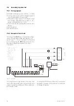
Страница 28: ... 4 2 Example of test circuit For testing of the XRN2 relay a three phase voltage source with adjustable voltage and frequency is re quired Figure 7 1 shows an example of a three phase test circuit energizing the XRN2 relay during test The three phase voltages are applied to the relay in Y connection Fig 7 1 Test circuit For testing the vector surge function of the relay a test circuit which can pr...

Страница 29: ...increase decrease the voltages until the relay starts i e at the moment when the LED U or U lights up or the voltage alarm output relay contact ter minals 31 34 and 41 44 is activated Read the op erating voltage indicated by the voltmeter The devia tion must not exceed 1 of the set operating value Furthermore gradually decrease increase the voltages until the relay resets i e the voltage alarm out...

Страница 30: ...se angle of the input voltage to change depending on the adjustable resistor R The phase angle obtained may be calculated with the following formula and is almost independent on the test voltages In case of a 3 phase vector surge the angle Θ can be calculated with the following formula if the parame ters R0 R and C are known Θ ω ω arctg 1 R C arctg 1 R R C 0 0 Example R0 1 Ohm R 363 Ohm C 3 µF the...

Страница 31: ... indicating and measuring functions the XRN2 relay may be tested in the manner of a primary injection test without extra ex penditure and time consumption In actual service for example the measured voltage and frequency values on the XRN2 relay display may be compared phase by phase with the concerned in dications of the instruments of the switchboard to verify that the relay works and measures co...

Страница 32: ...Max allowed interruption of the auxiliarxy supply without a facting the function of the device 50 ms Influences on voltage measuring Aux voltage in the range 0 8 UH UHN 1 2 no additional influences to be measured Frequency in the range 0 8 f fN 1 4 for fN 50 Hz 0 15 Hz Harmonics up to 20 of the 3rd harmonic 0 1 per percent of the 3rd harmonic up to 20 of the 5th harmonic 0 05 per percent of the 5t...

Страница 33: ...Hz Frequency measuring repeti tion T 2 99 Cycles 1 Frequency element 1 3 f1 f3 tf1 tf3 30 49 99 EXIT 50 01 70 Hz 1 40 59 99 EXIT 60 01 80 Hz 2 tf min 3 50 s EXIT 0 1 0 01 Hz 0 01 0 02 0 05 0 1 0 2 0 5 1 0 2 0 s 0 005 Hz 1 or 20 ms df dt Step df dt Measuring repetition df dt 0 2 10 Hz s EXIT 2 64 Periods 0 1 0 2 0 5 Hz s 1 0 1 Hz s Θ Θ 2 22 EXIT 1 1 Vector surge logic 1 3 1Ph 3Ph Voltage theshold f...

Страница 34: ...86 Making current max 20 A 16 ms mechanical life span 30 x 10 6 operating cycles electrical life span 2 x 10 5 operating cycles at 220 V AC 6 A Contact material silver cadmium oxide AgCdO 8 5 Power supply Auxiliary voltage 16 360 V DC 16 270 V AC Power consumption standby 3 W operating 5 W The connection terminals are C9 E9 Max allowed interruption of the auxiliarxy supply without effecting the fu...

Страница 35: ...EC 255 5 5 kV 1 2 50 µs 0 5 J High frequency interference test voltage inputs and outputs between themselves and to the relay frame as per EN 60255 6 IEC 255 6 2 5 kV 1 MHz Electrical discharge ESD test as per EN 61000 4 2 IEC 255 22 1 8 kV air discharge 6 kV contact discharge Electrical fast transient Burst test as per EN 61000 4 8 IEC 255 22 1 4 kV 2 5 kHz 15 ms Power frequency magnetic field im...

Страница 36: ...hange without notice 8 8 Relay case Relay XRN2 is designed to be fastened onto a DIN rail acc to DIN EN 50022 the same as all units of the PROFESSIONAL LINE The front plate of the relay is protected with a sealable transparent cover IP40 Fig 8 1 Dimensional drawing dimensions in mm Connection terminals The connection of up to a maximum 2 x 2 5 mm 2 cross section conductors is possible For this the...

Страница 37: ...TB XRN2 02 00 E 37 9 Order form Mains decoupling relay XRN2 with voltage frequency and vector surge supervision Voltage frequency and df dt supervision 1 2 Rated voltage 100 V 230 V 400 V 1 2 4 ...

Страница 38: ...270 480 tU tripping delay for overvoltage element s 0 04 fN rated frequency Hz 50 T frequency measuring repetition in periods cycles 4 f1 pickup value for frequency element 1 Hz 4800 tf1 tripping delay for frequency element 1 s 0 1 f2 pickup value for frequency element 2 Hz 4900 tf2 tripping delay for frequency element 2 s 0 1 f3 pickup value for frequency element 3 Hz 5100 tf3 tripping delay for ...

Страница 39: ...3 Θ df dt Default setting BLOC BLOC NO_B NO_B BLOC BLOC NO_B BLOC BLOC Actual setting Setting of dip switches Dip switch 1 2 3 4 Default setting Actual setting Default setting Actual setting Default setting Actual setting Default setting Actual setting ON OFF X X X X ...

Страница 40: ...40 TB XRN2 02 00 E ...

Отзывы: