4
TB XRN2 02.00 E
3
Design
3.1
Connections
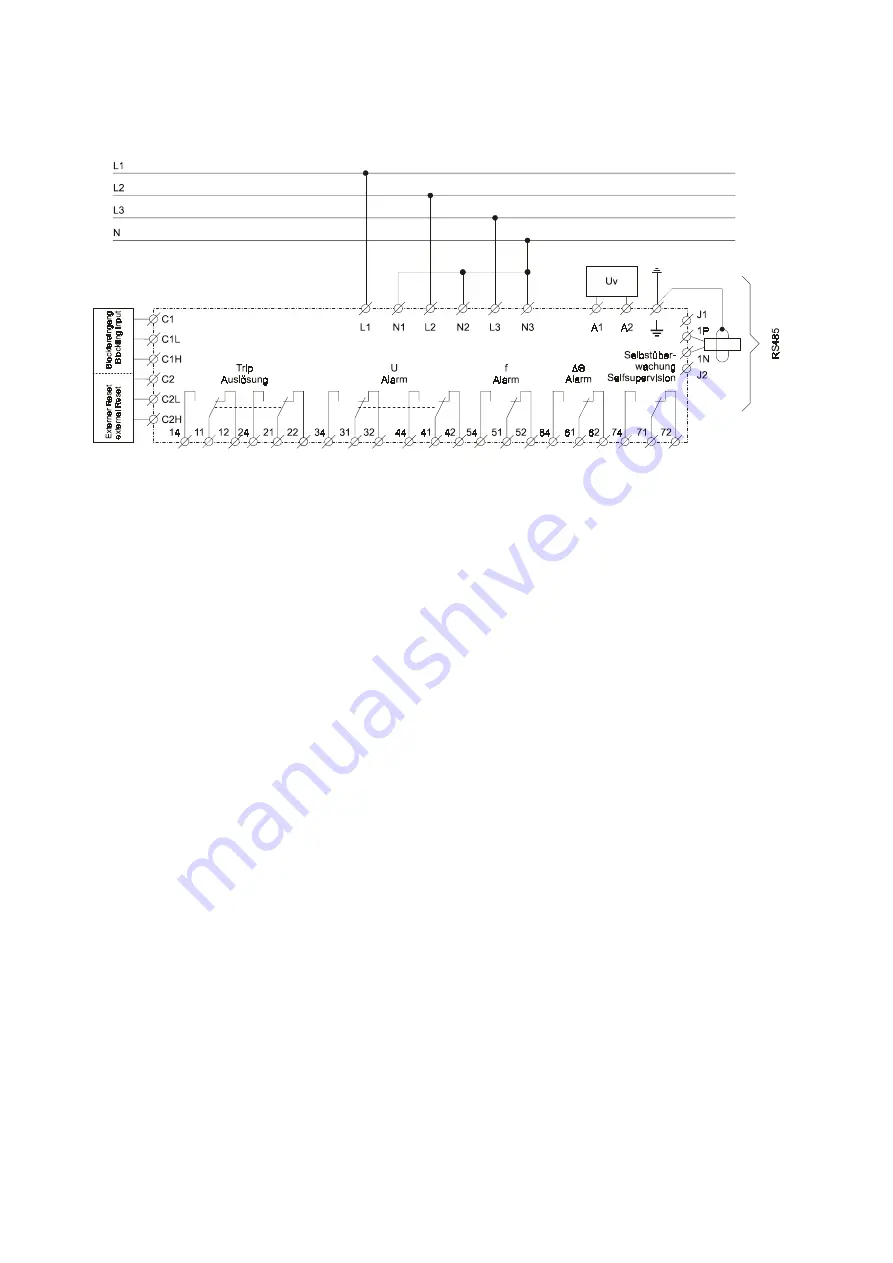
Fig.3.1: Connection diagram
XRN2-1
and
XRN2-2
3.1.1
Analog input circuits
The analog input voltages are galvanically decoupled
by the input transformers of the device, then filtered and
finally fed to the analog digital converter. The measur-
ing circuits can be applied in star or delta connection
(refer to chapter 4.3.1).
3.1.2
Blocking input
The blocking function can be set according to require-
ment. By applying the auxiliary voltage to C1/C1L or
C1/C1H, the previously set relay functions are
blocked (refer to 4.8 and 6.2.10).
3.1.3
Reset input
Please refer to chapter 6.4.
3.1.4
Output relays
The
XRN2
has 5 output relays. One trip relay with two
changeover contacts. One alarm relay with two
changeover contacts and three alarm relays with one
changeover contact.
•
Tripping 11, 12, 14 and 21, 22, 24
•
Indication of over-/ and undervoltage alarm
31, 32, 34 and 41, 42, 44
•
Indication of over-/ and underfrequency alarm
51, 52, 54
•
Indication of vector surge 61, 62, 64 (
XRN2-1
) or
df/dt-alarm (
XRN2-2
)
•
Indication self supervision (internal fault of the unit)
71, 72, 74
All trip and alarm relays are normally-off relays, the re-
lay for self supervision is a normally-on relay.
Содержание XRN2
Страница 1: ...XRN2 Mains decoupling relay ...
Страница 40: ...40 TB XRN2 02 00 E ...


